


Special offers from our partners!

Find Replacement BBQ Parts for 20,308 Models. Repair your BBQ today.

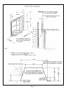
The two slots in the rear of the base of the firebox may be used to secure the appliance in position. Where no spacer is
used the unit will require securing at the top using the two holes in the top corner plate and the No 10 c/sk screws
provided. This is needed to effect a seal with the flue.
Vent Box Installed with Spacer frame
a. 6 holes are provided in the rear of the spacer frame with access through the front of the frame. Only 4 fixing positions
are required, 1 at the bottom of each leg and 2 others in either of the top of the left or right hand legs.
b. Holes in the side of the spacer frame for self tap screws for side fixing - 4 holes in the front flange for 16in openings
and 4 holes in the rear for 18in openings.
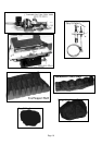
Installing the Appliance in Position
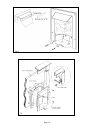
With the gas supply pipe laid to the position required the surround should be fitted and sealed to the chimney correctly,
this is to prevent any seepage of flue products or to prevent any ingress of air into the flue from anywhere other than the
flue outlet of the fire. A decision would have been made earlier as to whether or not the spacer will be required. The
easier method of installation is through the 6 holes provided in the spacer frame or through the four holes in the front face
of the vent box - both methods will require drilling into the back panel of the surround. See fig 5. Where it is undesirable
to deface or damage the back panel, 4 fixing straps are provided which can be fastened to the inner walls of the opening
and the inner flanges. See fig 5.
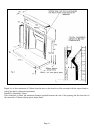
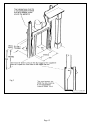
If a spacer frame is not used an alternative method is to screw through the 2 slots provided in the base or rough the two
holes in the rear panel, using the countersunk woodscrews provided. In addition it may be necessary to use the top two
fixing holes in the corners of the vent box. An additional length of sealing strip is included in the fixing kit to allow an
extra thickness to be added where it is necessary to effect a seal on uneven surfaces. Remove the backing strip covering
the adhesive surface of the strip and position onto the rear of the firebox or the spacer frame where applicable.
Before offering the vent box into the opening, the hearth should be protected from damage or scratches that may occur
during installation.
Locate and secure the vent box by the method chosen ensuring that a good seal exists with the back panel. Lay a gas
supply to the location of the burner connecting elbow and place the burner into the vent box locating the feet of the rear
legs into the two tags in the base. Secure the position with the 2 x No. 8 self tap screws supplied and complete the gas
connection.
Fit the brass trim in position with the magnets provided and remove the plastic coating from the brass.
Note: The complete installation should be tested for gas soundness.
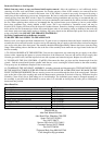
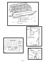
Laying the Coal Bed
The coal support shelf is positioned on the fibre support metalwork; two stops prevent the shelf sitting on the burner outlet.
Place the simulated coal front in the position shown in Fig.6. The one-piece support shelf is constructed to allow three levels
of coal support; these three levels are shown in Fig 6, the plan view of the bed.
Coal Layout (See Figs 6 - 9)
First Layer.
Position 3 large coals and 6 small coals between the front simulated coal and the lower level of the coal support
shelf. Ensure the gap indicated is left clear to view the pilot flame.
Place 3 large coals on the middle level of the coal support shelf as shown.
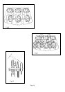
Second Layer. Place 4 small coals in position to fill gaps between the coals on the lower and middle level of the coal support
shelf
Place 2 small coals in position to straddle the 3 large coals on the middle level and upper level of the coal support shelf..
To obtain the best visual appearance it may be necessary to make slight adjustments to the positions of the coals.
NOTE: If any of the coals or coal bed become damaged, lost or broken, genuine manufacturer’s replacement parts must be
obtained before the appliance is used.
Page 7