


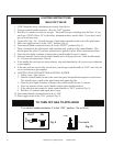
Special offers from our partners!

Find Replacement BBQ Parts for 20,308 Models. Repair your BBQ today.
8 Quadra-Fire • Fogata Grande October 2006
4
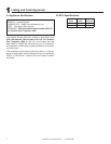
Appliance Set Up
1)AfterplacingtheFogataGrandeinthedesiredlocation,
locatetheovalholeintherebowlandbesureitisposi-
tionedtowardsthelegwherethegasconnectionistobe
made.
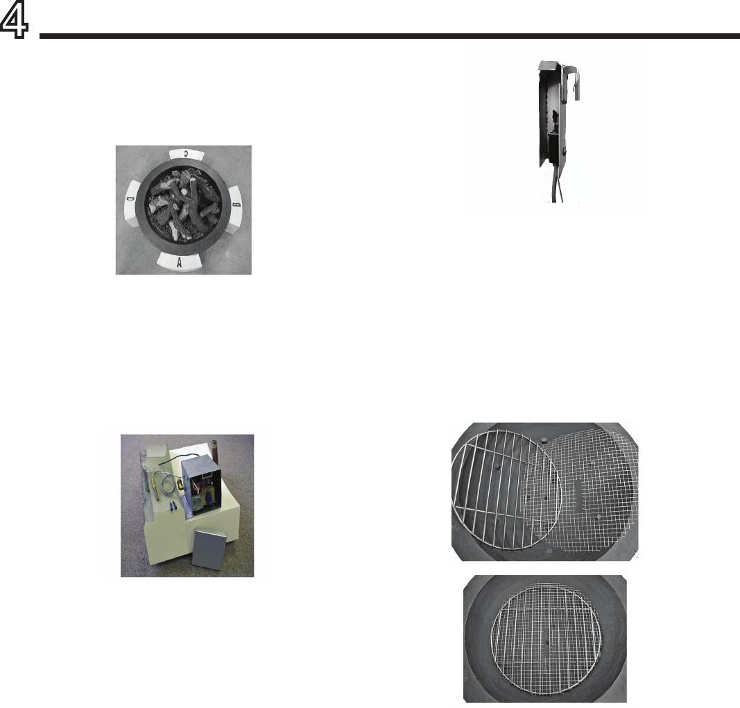
2)Withthelettersprovided,usingtape,identifyleg“A”as
thelegtowhichthegasvalveassemblywillbeattached.
Movingcounterclockwise,labletheremaininglegs“B”,“C”
and“D”asshowninFigure1.Thiswillassityouininstalling
thelogsafterthegasconnectionshavebeenmade.
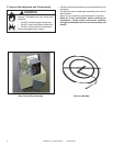
3)AsshowninFigure2,layleg“A”onitsface(onasmooth
nonabrasivesurfacetopreventdamagingthesurface)to
begintheassemblyofthegassystem.
Asshow,placethegasvalvecontrolboxontheinsideofleg
“A”.Locatetheopenendoftheboxassembly1/2inchback
fromtheedgeofthelegasshowninFigure1.
Nextpositionthetopangewiththetwokeyholeanchor
-
ingholesapproximately3/4inchdownfromtheseamas
shown.Pre-Drilltheholeswithamasonrydrillbitandse-
curethetwomasonryscrewsthroughthetopoftheholes
providedintotheleg.Donotcompletelytightensincethe
controlboxwillneedtoberemovedinordertocompletethe
nalinstallation.
Once the screws have been installed, remove the valve
controlboxinordertoassembletheothercomponenets.
Figure 2
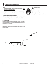
4)Foryourconvenience,thePilotassembly,Figure3,may
havealready beeninstalledon burner. Intheevent that
thePilotassemblyisnotinstalled,locatethecrosssection
oftheburnerwiththecoloredhighlight.(thiswillbeonthe
innerringatthecrosssection.Notetheport-holeswillbe
facingdown).InsertthePilothoodbracketovertheburner
tubeandslideitforwardsothetopfrontclipslidesoverthe
tubeoftheburnerandcoversthehighlightedmarkingson
theburnertube.Inordertoassembletheunit,thePilothood
bracketmayneedtobeinsertedatanangleandtwistedinto
placetoensurethattheunitisinitsproperposition.
Figure 3
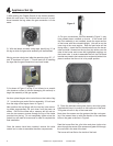
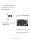
5)Placethestainlesssteelgrate(heavyroundbargrate,
suppliedwithrepit)inpositioninthelowerpartofthebowl.
Thisgratewillrestontopofthelowertabs.
Nextplacethescreenoverthegratesothattheovalopen-
inginthescreenlinesupwiththedirectionofthestainless
barsonthegrateasshowninFigure4.
Feedtheburnerexline,pilottubeandpiezoignitorwire
downthroughthecenterofthescreenandgrateandthrough
theovalholeinthesideofthebowl
Theburnerwillrestatontheinsideofthebowl.
Figure 4
Figure 1