


Special offers from our partners!

Find Replacement BBQ Parts for 20,308 Models. Repair your BBQ today.

DATE PRINTED: 2/8/05 Revision Date: 02/01/05 PI-1010A Page 19
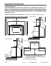
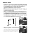
3) Exact placement of the insert is determined by the overall shape of your fireplace opening and surround etc.
First determine whether you will need leveling bolts installed or other devices to ensure a proper level instal-
lation of the unit. This is determined by your fireplace construction. Sometimes the hearth is raised from the
bottom of the fireplace and sometimes it is lower. Use only non-combustible material to fill any space under
the insert (such as firebricks). The insert must sit level with or slightly higher than the hearth front.
On each corner of the underside of the fireplace insert there is a 3/8” NC nut welded. If required a 3/8” bolt of
determined length can be threaded into these nuts to assist in leveling the unit.
NOTE: Blaze King strongly recommends that you install a complete stainless steel flue liner system. This is
the safest installation and will ensure proper draft control for best burn and consistency. The aforementioned
liner system is required by code for all installations in Canada, the installation codes in some USA locations
do not require a full stainless steel liner system.
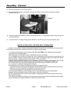
4) Slide the unit into the fireplace opening and attach the chimney liner or flue connector system as required,
working through the opening above the unit where the top shroud panel will fit, next step. If access to the
flue outlet on the insert is very restricted by fireplace opening height you may need to temporarily remove a
side panel (as fitted in step 2) to allow work area to properly connect the stainless steel flue liner. Depending
upon the particular installation the unit may need to be pulled out slightly from the front of the fireplace.
In some installations the leveling bolts might make it difficult to slide the unit into the fireplace, due to a rough
hearth. We have provided two metal strips approximately 3" x 16" to help ease this problem. Lay the strips
down and slide the unit on them, this is only a suggestion and may mot be required in all circumstances. If
they are not required discard the strips. We hope they help you its a heavy job!!
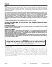
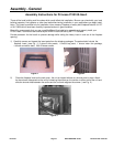
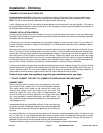
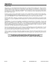
5) Assemble the shroud trim as shown in Fig 4. It will be attached to the
unit during the next step.
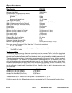
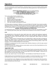
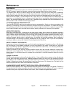
6) Place the shroud top on the unit sliding it down so the tabs on the back
of the part slide over the tabs on the insert.
7) Hold the shroud top panel in place and slide the trim down over the
shroud sides and top (see Fig. 6). Secure the trim in place with 2 #6-
32 brass creek screws provided.
Left
L-Brackets X2
Top
Right
Brass Screws X4
Screw
Screw
Figure 4
Assembly - General
Figure 5
Figure 6