


Special offers from our partners!

Find Replacement BBQ Parts for 20,308 Models. Repair your BBQ today.

16
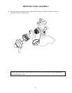
GAS HOOK-UP
Only the pressure regulator and hose assembly supplied
with the grill should be used. Any replacement pressure
regulator and hose assembly must be specified by the
grill manufacturer.
This is a propane configured grill. Do not attempt to use
a natural gas supply unless the grill has been
reconfigured for natural gas use.
Total gas consumption (per hour) of the 720-0230
(Charmglow) Grill with all burners on “HI”:
Main burners 36,000 Btu/hr.
Side burner 12,000 Btu/hr.
Total 48,000 Btu/hr.
The installation of this appliance must conform with
local codes or, in the absence of local codes, with the
national fuel gas code, ANSI Z223. 1a-1988. Installation
in Canada must be in accordance with the Standard
Can1-b149.1 and/or .2 (installation code for gas burning
appliances and equipment) and local codes.
L.P. Tank Requirements
A dented or rusty L.P. tank may be hazardous and should
be checked by your L.P. supplier. Never use a cylinder
with a damaged valve. The L.P. gas cylinder must be
constructed and marked in accordance with the
specifications for L.P. gas cylinders of the U.S.
Department of Transportation (DOT), or the National
Standard of Canada, CAN/CSA-B339, Cylinders,
Spheres and Tubes for Transportation of Dangerous
Goods; and Commission.
The cylinder must be provided with a shut valve
terminating in an L.P. gas supply cylinder valve outlet
specified, as applicable, for connection type QCC1 in the
standard for compressed gas cylinder valve outlet and
inlet connection ANSI/CGA-V-1.
The cylinder supply system must be arranged for vapor
withdrawal. The cylinder must include a collar to protect
the cylinder valve.
Manifold pressure: (operating): 10” water column
(W.C.), (non-operating): 11.2” water column (W.C.).
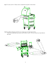
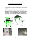
L.P. GAS HOOK-UP:
Ensure that the black plastic grommets on the LP
cylinder valve are in place and that the hose does not
come into contact with the grease tray or the grill head.
CONNECTION:
Your 720-0230 (Charmglow) grill is equipped with gas
supply orifices for use only with propane gas. It is also
equipped with a high capacity hose/regulator assembly
for connection to a standard 20lb. L.P. cylinder (18-1/4”
high, 12-1/4” diameter).
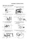
To connect the L.P. gas supply cylinder, please follow
the steps below:
1. Make sure tank valve is in its full off position (turn
clockwise to stop)
2. Check tank valve to assure it has proper external
male threads (type 1 connection per ANSIZ21.81)
3. Make sure all burner valves are in their off position.
4. Inspect valve connections, port, and regulator
assembly. Look for any damage or debris. Remove
any debris. Inspect hose for damage. Never attempt
to use damaged or obstructed equipment. See your
local L.P. gas dealer for repair.
5. When connecting regulator assembly to the valve,
hand tighten the nut clockwise to a complete stop.
Do not use a wrench to tighten. Use of a wrench
may damage the quick coupling nut and result in a
hazardous condition.
6. Open the tank valve fully (counterclockwise). Use a
soapy water solution to check all connections for
leaks before attempting to light the grill, see below.
If a leak is found, turn the tank valve off and do not
use the grill until a local L.P. gas dealer can make
repairs.
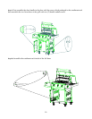
To disconnect L.P. gas cylinder:
1. Turn the burner valves off.
2. Turn the tank valve off fully (turn clockwise to
stop).
3. Detach the regulator assembly from the tank valve
by turning the quick coupling nut counterclockwise.
LEAK TESTING
GENERAL
Although all gas connections on the grill are leak tested
at the factory prior to shipment, a complete gas tightness
check must be performed at the installation site due to
possible mishandling in shipment, or excessive pressure
unknowingly being applied to the unit. Periodically
check the whole system for leaks following the
procedures listed below. If the smell of gas is detected at
anytime you should immediately check the entire system
for leaks.