


Special offers from our partners!

Find Replacement BBQ Parts for 20,308 Models. Repair your BBQ today.
W415-0530 / 12.14.05
5
2
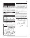
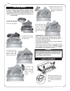
1. With the 2 andirons laying face down,
secure the grate overtop using 2x ¼-20
bolts (supplied in the manual baggie).
2. Install the grate/andiron assembly to the
burner base using 4x ¾” self tapping screws
(supplied in the manual baggie).
ANDIRON & GRATE ASSEMBLY
Use only accesso-
ries designed for and
listed with your
specific log set.
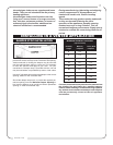
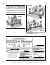
AIR SHUTTER
TESGOL RETTUHSRIA
LEUF
GN PL
81LFVG
9
/
23
"
5
/
61
"
42LFVG
9
/
23
"
5
/
61
"
03LFVG
9
/
23
"
5
/
61
"
The air shutter settings are factory set for most installations.
However, adjustment may be required depending on fuel
type, vent performance and altitude.
Closing the air shutter will cause a more yellow flame, but
can lead to carboning. Opening the air shutter will cause a
more blue flame, but can cause flame lifting from the burner
ports. The flame may not appear yellow immediately; allow
15 to 30 minutes for the final flame colour to be established.
MINIMUM FIREPLACE SIZE
TESGOL THGIEH HTDIW HTPED
"81
81LFVG
"81"22"41
"42
42LFVG
"02"82"61
"03
03LFVG
"22"43"02
Each gas log set must be installed into a fireplace cavity
with a minimum size.
Refer to the table below to determine the appropriate mini-
mum fireplace size.
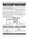
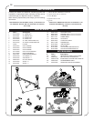
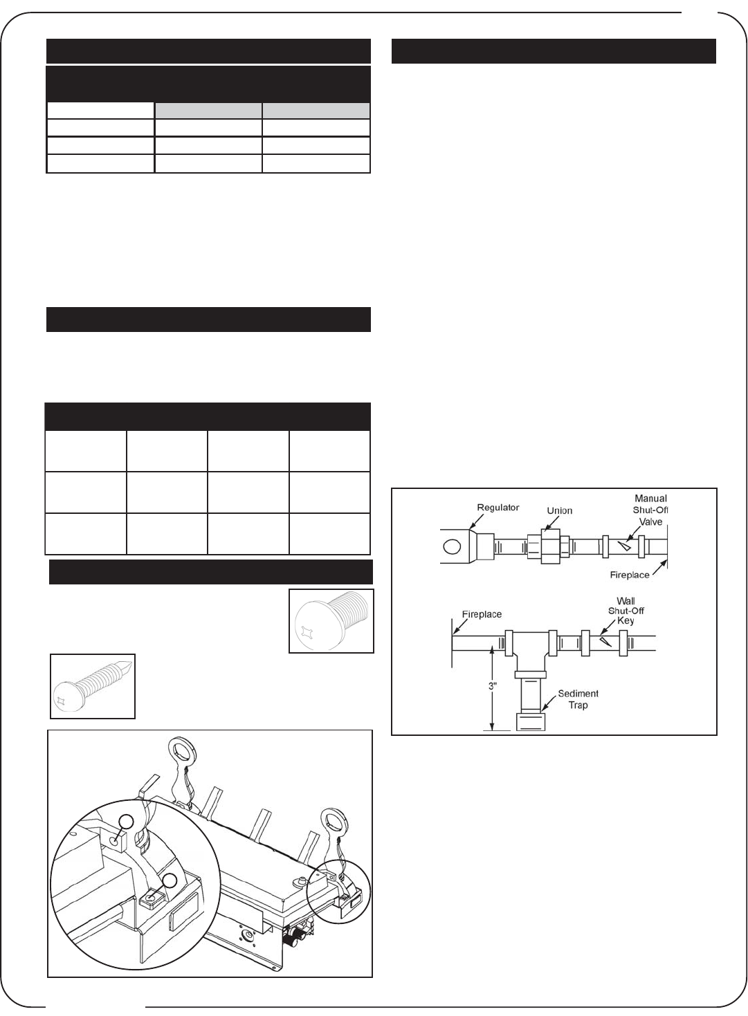
1
This appliance must be isolated from the gas supply pip-
ing system by closing the individual manual shut off valve
during any pressure testing of the gas supply piping sys-
tem at test pressure equal to or less than ½ psi (3.5 kPa)
1. Centre the appliance in the fireplace opening, making
sure the appliance has enough room behind it for the gas
line to run behind the log set under the log support.
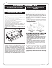
2. Route the gas line and sizing using piping ½” diameter
or greater to allow the full volume of gas to the appliance.
The routing of the gas line has to be done to local and / or
national codes.
3. When rigid pipe is used an ANSI approved manual shut
off and a union must be installed upstream within the fire-
place cavity.
4. To ensure the appliance operates reliably install a sedi-
ment trap upstream of the appliance within the structures of
the piping system.
5. When using propane, a regulator must be used between
the tank and the outside wall of the house to ensure the line
pressure does not exceed 14” w.c.
6. Check gas connections with a gas detection device to
test for leaks in the system. Soapy water mixture can also
be used to check for leaks.
7. Once all the gas connections are tested for leaks, start
the appliance. Follow the lighting instructions to ensure
the appliance is working properly before finishing.
GAS PIPING