


Special offers from our partners!

Find Replacement BBQ Parts for 20,308 Models. Repair your BBQ today.
5
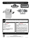
www.napoleongrills.com
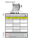
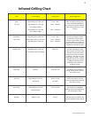
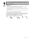
Leak Tesng Instrucons
WARNING! A leak test must be performed annually and each me a cylinder is hooked up or if a part
of the gas system is replaced.
WARNING! Never use an open ame to check for gas leaks. Be certain no sparks or open ames are
in the area while you check for leaks. Sparks or open ames will result in a re or explosion, damage to
property, serious bodily injury, or death.
Leak tesng: This must be done before inial use, annually, and whenever any gas components are replaced
or serviced. Do not smoke while performing this test, and remove all sources of ignion. See Leak Tesng
Diagram for areas to check. Turn all burner controls to the o posion. Turn gas supply valve on.
Brush a half-and-half soluon of liquid soap and water onto all joints and connecons of the regulator, hose,
manifolds and valves.
Bubbles will indicate a gas leak. Either ghten the loose joint or have the part replaced with one recommend
ed
by the Napoleon Customer Care department and have the grill inspected by a cered gas installer.
If the leak cannot be stopped, immediately shut o the gas supply, disconnect it, and have the grill inspected
by a cered gas installer or dealer. Do not use the grill unl the leak has been corrected.
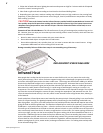
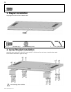
Natural Gas Hook-Up
This natural gas grill is supplied with a 10 supply hose (complete with a quick disconnect) designed for natural gas and
cered for outdoor use. The gas grill is designed to operate at an inlet pressure of 7 inches water column. Piping and
valves upstream of the quick disconnect are not supplied. The installaon must comply with CAN B149.1 Natural Gas and
Propane installaon code in Canada, or to the Naonal Fuel Gas Code, ANSI Z223.1 in the United States.
The gas supply
pipe must be suciently sized to supply the BTU/h specied on the rang plate, based on the length of the
piping run.
The quick disconnect must not be installed in an upward direcon and a readily accessible manual shut-o
valve must be installed upstream of, and as close to, the quick disconnect as is feasible. The ared end of the
hose must be connected to the ng on the end of the ex tube as illustrated in the Natural Gas Hose Aach
ment
diagram. Tighten using two wrenches. (Do not use thread sealer/pipe dope.) These connecons must be
made by a licensed gas installer. Leak test all joints prior to using the gas grill.
WARNING!
• The installaon must be performed by a licensed gas er, and all connecons must be leak tested before
operang the grill.
• Do not route hose underneath drip pan.
• Do not route hose between space in boom shelf and back panel.
• Do not route hose over top of back panel.
• Ensure all hose connecons are ghtened using two wrenches. Do not use teon tape or pipe dope on
any hose connecon.
• Ensure the hose does not contact any high temperature surfaces, or it may melt and leak causing a re.
• Do not use enclosure to store excess hose, as there is a greater chance of the hose contacng a hot surface,
it may melt and leak causing a re.
• Leak test all the connecons using a soap and water soluon, as per the leak tesng instrucons found in
the this manual.