


Special offers from our partners!

Find Replacement BBQ Parts for 20,308 Models. Repair your BBQ today.
6
W415-0377 / 03.04.03
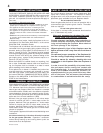
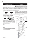
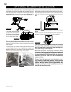
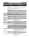
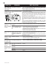
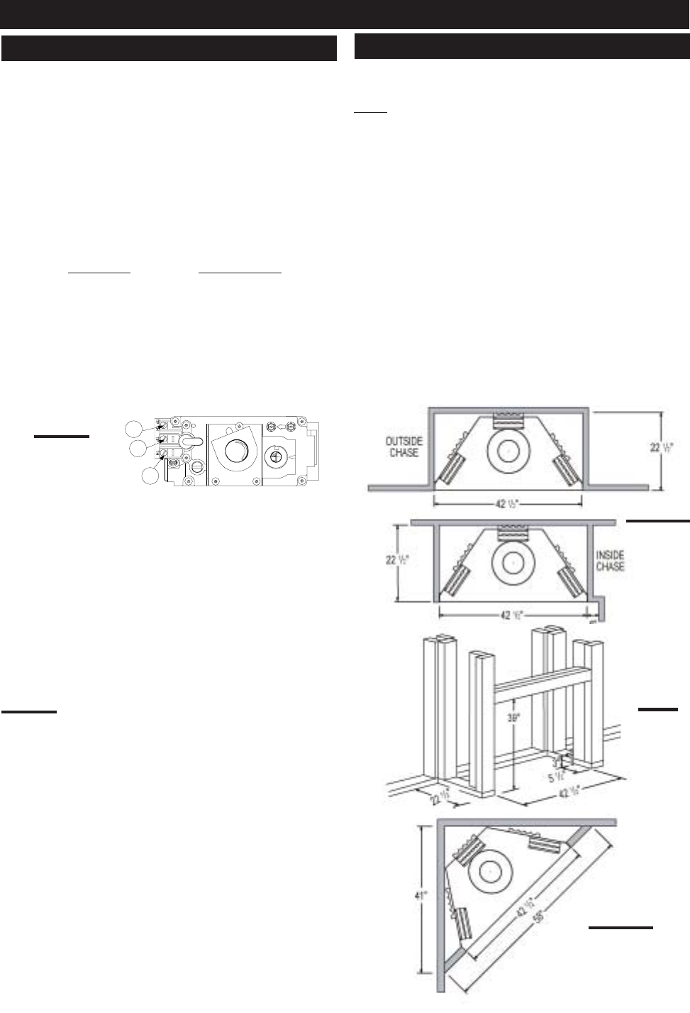
It is best to frame your fireplace after it is positioned. Use
2x4's and frame to local building codes. FIGURE 7-9.
Note: In order to avoid the possibility of exposed insulation
or vapour barrier coming in contact with the fireplace body,
it is recommended that the walls of the fireplace enclosure
be “finished” (ie: drywall/sheetrock), as you would finish
any other outside wall of a home. This will ensure theat
clearance to combustibles is maintained within the cavity.
It is not necessary to install a hearth extension with this
fireplace system.
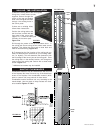
When roughing in the fireplace, raise the fireplace to ac-
commodate for the thickness of the finished floor materi-
als, i.e. tile, carpeting, hard wood, which if not planned for
will interfere with the opening of the lower access door and
the installation of many decorative flashing accessories.
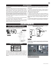
Objects placed in front of the fireplace should be kept a
minimum of 4 feet away from the front face.
Minimum clearance to combustible con-
struction from fireplace:
sides, back, bottom and top of the unit 0 inch
recessed depth 22 inches
Proceed once the vent installation is complete.
1. Move the fireplace into position and secure using the
nailing tabs and/or secure to the floor through the 1/4"ø
holes located at either end of the base.
2. Route a 3/8" N.P.T. black iron gas line, 1/2" type-L cop-
per tubing or equivalent to the fireplace.
3. For ease of accessibility, an optional remote wall switch
or millivolt thermostat may be installed in a convenient lo-
cation. Route 2-strand (solid core) millivolt wire through
the electrical hole located at the bottom left side of the unit.
The recommended maximum lead length depends on wire
size:
WIRE SIZE MAX. LENGTH
14gauge 100 feet
16gauge 60 feet
18gauge 40 feet
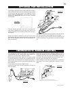
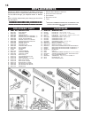
Attach the one lead to terminal 3 (located on the gas valve)
and the other lead to the vent safety switch wire ( located
loose in the valve compartment). See FIGURE 3.
Do not connect either the wall switch, thermostat
or gas valve to electricity (110 volts).
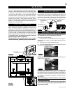
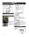
4. Install rigid black pipe, 1/2" type-L copper tubing or, if
local codes permit, a 3/8" flex connector and shutoff valve
to the gas line and the fireplace gas valve. Seal and tighten
securely. An adapter fitting is required between the gas
valve and the copper tubing or flex connector. DO NOT KINK
FLEXIBLE CONNECTOR. FIGURE 6.
5. Check for gas leaks by brushing on a soap and water
solution.
Do not use open flame.
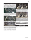
Purge all gas lines with the glass door of the fireplace
removed. Assure that a continuous gas flow is at the
burner before installing the door.
FIGURE 7
P
I
P
I
L
O
T
3
1
2
N
O
L
O
T
H
I
L
O
F
F
O
FIGURE 6
FIGURE 9
FIGURES 8
GAS INSTALLATION
FRAMING
INSTALLATION
FIGURE 10