


Special offers from our partners!

Find Replacement BBQ Parts for 20,308 Models. Repair your BBQ today.
15
W415-0244 / A / 05.15.03
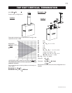
FIGURE 25
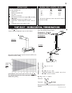
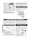
The vent system must be supported approximately every 3
feet for both vertical and horizontal runs. Use Wolf Steel
vent spacers every 3 feet and either side of each elbow to
maintain the minimum 1¼" clearance between the outer
and inner vent pipes. Use Wolf Steel support ring assem-
bly or equivalent noncombustible strapping to maintain the
minimum clearance to combustibles for both vertical and
horizontal runs.
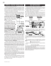
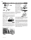
1. Move the fireplace into position. Meas-
ure the vent length required between ter-
minal and fireplace taking into account
the additional length needed for the finished wall surface and
any 1¼" overlaps between venting components.
2. Apply high temperature sealant to the outer edge of the 5"
inner collar of the fireplace. Attach the first vent component and
secure using 3 self tapping screws. Repeat using 8" piping.
3. Holding the air terminal (with the air deflectors to the
top), insert into both vent pipes with a twisting motion to ensure
that both the terminal sleeves engage into the vent pipes and
sealant. Secure the terminal to the exterior wall and make
weather tight by sealing with caulking (not supplied).
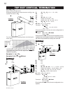
The air terminal mounting plate may be recessed into the
exterior wall or siding by 1½", the depth of the return flange.
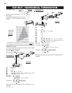
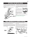
1. Follow the instructions for "Horizontal Air Terminal In-
stallations", items 1 to 3.
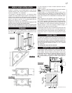
2. Continue adding components alternating inner and
outer venting. Ensure that all 5" venting and elbows have
sufficient vent spacers attached and each component is
securely fastened to the one prior. Attach the 5" telescopic
sleeve to the vent run.
Repeat using a 8" tel-
escopic sleeve. Secure
and seal as before. To
facilitate completion, at-
tach 5" and 8" couplers
to the air terminal.
3. Install the air terminal. See item 3 of
the Horizontal Air Terminal Installation.
Extend the 5" telescopic sleeve; connect
to the air terminal assembly. Fasten with
self tapping screws and seal. Repeat
using the 8" telescopic sleeve.
TELESCOPIC SLEEV
VENTING
20"
COUPLER
AIR TERMINAL
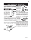
FIGURE 26
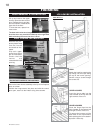
Do not nail through
the lower portion of the
flashing. Make
weather-tight by seal-
ing with caulking.
Where possible, cover
the sides and top
edges of the flashing
with roofing material.
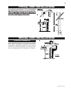
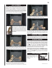
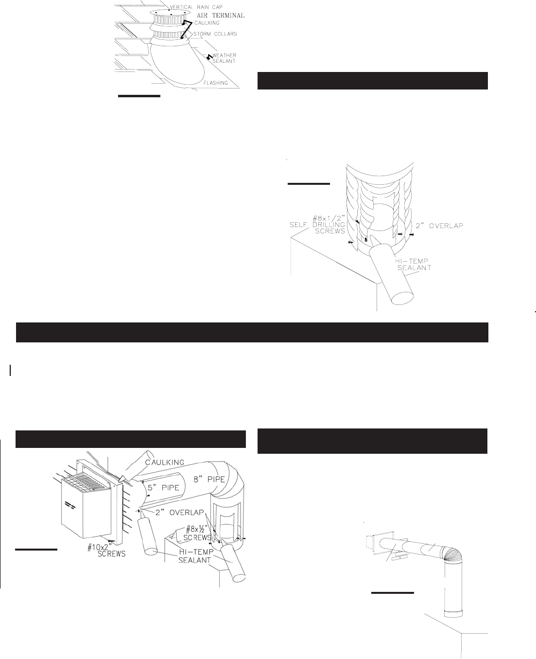
6. Apply a heavy
bead of weatherproof caulking 2 inches above the flash-
ing. Slide the storm collar around the air terminal and down
to the caulking. Tighten to ensure that a weather-tight seal
between the air terminal and the collar is achieved. Attach
the other storm collar centered between the air intake and
the air exhaust slots onto the air terminal. Tighten securely.
FIGURE 23. Attach the vertical rain cap.
Spacers are attached to the 5" inner flex liner at prede-
termined intervals to maintain a 1-1/4" air gap to the 8"
outer liner. These spacers must not be removed.
7. If more liner needs to be used to reach the fireplace,
follow the same procedure as found in EXTENDED HORI-
ZONTAL AIR TERMINAL INSTALLATION. The vent system
must be supported approximately every 3 feet for both ver-
tical and horizontal runs. Use Wolf Steel support ring as-
sembly or equivalent noncombustible strapping to main-
tain a clearance to combustibles.
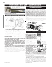
1. Install the 5 inch diameter aluminium flexible liner to
the fireplace. Secure with 3 screws and flat washers. Seal
the joint and screw holes using the high temperature seal-
ant provided. FIGURE 24.
2. Install the 8 inch diameter aluminium flexible liner to
the fireplace. Attach and seal the joints.
FIGURE 24
FIGURE 23
FIREPLACE VENT CONNECTION
USING RIGID VENT COMPONENTS
HORIZONTAL AIR TERMINAL INSTALLATION
EXTENDED HORIZONTAL AND CORNER
AIR TERMINAL INSTALLATION