


Special offers from our partners!

Find Replacement BBQ Parts for 20,308 Models. Repair your BBQ today.
14
W415-0244 / A / 05.15.03
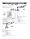
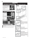
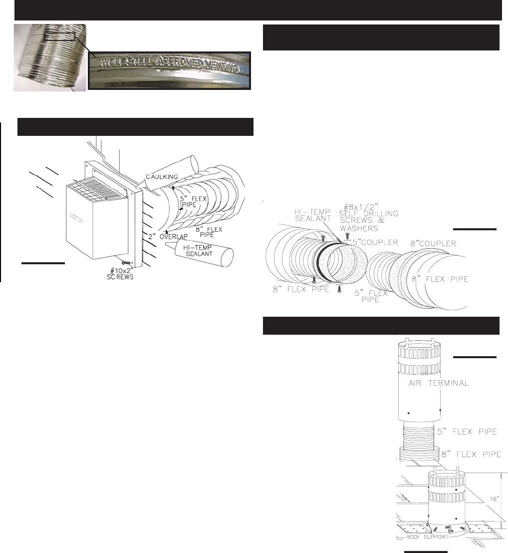
Use only approved aluminum flexi-
ble liner kits marked:
"Wolf Steel Approved Venting" as identified by the
stamp only on the 8” outer liner.
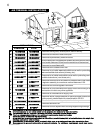
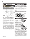
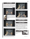
1. Cut or frame a hole in an exterior wall with a minimum
round or square opening listed on page 5. Secure the
firestop spacer over the opening to the interior wall.
2. Stretch the 5" diameter aluminum flexible liner to the
required length taking into account the additional length
needed for the finished wall surface. Slip the liner a mini-
mum of 2" over the inner sleeve of the air terminal and
secure with 3 #8 screws. Apply a heavy bead of the high
temperature sealant.
3. Using the 8" diameter flexible aluminum liner, slide
over the outer combustion air sleeve of the air terminal and
secure with 3 #8 screws. Seal as before.
4. Insert the liners through the firestop maintaining the
required clearance to combustibles. Holding the air termi-
nal (lettering in an upright, readable position), secure to
the exterior wall and make weather tight by sealing with
caulking (not supplied).
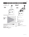
5. Apply a heavy bead of the high temperature sealant,
supplied with the unit, to the inside of the 5" liner approxi-
mately 1" from the end. Slip the liner a minimum of 2" over
the fireplace vent collar and secure with 3 #8 screws.
6. Using the 8" diameter flexible aluminium liner, apply
sealant, slide a minimum of 2" over the fireplace combus-
tion air collar and secure with 3 #8 screws.
FIGURE 19
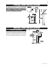
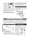
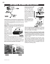
Use the GD420 vent kit and couplers for this application.
If more than one length of liner needs to be used to reach
the fireplace, couple them together as illustrated in
FIGURE 20. Seal the joints using the same procedure as
described in points 2 and 3. The vent system must be sup-
ported approximately every 3 feet for both vertical and hori-
zontal runs. Use Wolf Steel support ring assemblies, or
equivalent noncombustible strapping to maintain the mini-
mum 1" clearance to combustibles as well as to prevent
sagging.
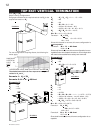
Spacers are attached to the 5" inner flex liner at prede-
termined intervals to maintain a 1-1/4" air gap to the 8"
outer liner. These spacers must not be removed.
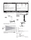
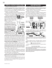
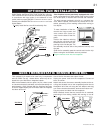
1. Fasten the roof support to
the roof using the screws pro-
vided. FIGURE 21. The roof sup-
port is optional. In this case the
venting is to be adequately sup-
ported using either an alternate
method suitable to the authority
having jurisdiction or the op-
tional roof support.
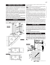
2. Stretch the 5" diameter alu-
minium flexible liner to the re-
quired length. Slip the liner a
minimum of 2" over the inner
sleeve of the air terminal and se-
cure with 3 #8 screws. Seal us-
ing a heavy bead of the high
temperature sealant.
3. Repeat using the 8" diam-
eter flexible aluminium liner.
4. Thread the air terminal pipe assembly down through
the roof. The air terminal must be located vertically and
plumb. Attach the air terminal assembly to the roof support,
ensuring that a minimum 16" of air terminal will penetrate
the roof when fastened.
DO NOT CLAMP THE FLEXIBLE ALUMINIUM LINER.
5. Remove nails from the shingles, above and to the
sides of the chimney. Place the flashing over the air termi-
nal and slide it underneath the sides and upper edge of
the shingles. Ensure that the air terminal is properly
centered within the flashing, giving a 3/4" margin all around.
Fasten to the roof.
FIGURE 20
FIGURE 22
FIGURE 21
USING FLEXIBLE VENT COMPONENTS
HORIZONTAL AIR TERMINAL INSTALLATION
EXTENDED HORIZONTAL
AIR TERMINAL INSTALLATION
VERTICAL AIR TERMINAL INSTALLATION