


Special offers from our partners!

Find Replacement BBQ Parts for 20,308 Models. Repair your BBQ today.
13
W415-0244 / A / 05.15.03
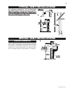
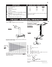
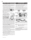
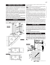
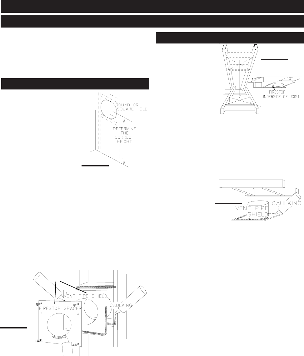
This application occurs
when venting through a
roof. Installation kits for
various roof pitches are
available from your Na-
poleon dealer. See Ac-
cessories to order the
specific kit required.
1. Determine the air
terminal location, cut
and frame 10 inch open-
ings in the ceiling and the roof to provide the minimum 1
inch clearance between the fireplace pipe / liner and any
combustible material. Try to center the exhaust pipe loca-
tion midway between two joist to prevent having to cut them.
Use a plumb bob to line up the center of the openings. DO
NOT FILL THIS SPACE WITH ANY TYPE OF MATERIAL. A
vent pipe shield will prevent any materials such as insula-
tion, from filling up the 1" air space around the pipe. Nail
headers between
the joist for extra
support.
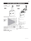
2. Apply a bead of
caulking (not sup-
plied) to the frame-
work or to the Wolf
Steel vent pipe
shield plate or equivalent (in the case of a finished ceiling),
and secure over the opening in the ceiling. FIGURE 18. A
firestop must be placed on the bottom of each framed open-
ing in a roof or ceiling that the venting system passes
through. Apply a bead of caulking all around and place a
firestop spacer over the vent shield to restrict cold air from
being drawn into the room or around the fireplace. Ensure
that both spacer and shield maintain the required clear-
ance to combustibles. Once the vent pipe / liner is installed
in its final position, apply sealant between the pipe / liner
and the firestop spacer.
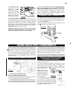
FIGURE 18
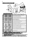
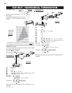
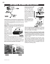
FOR SAFE AND PROPER OPERATION OF THE FIREPLACE,
FOLLOW THE VENTING INSTRUCTIONS EXACTLY.
A HEAT SHIELD MUST BE USED IF THE WALL TERMINAL IS
INSTALLED ON COMBUSTIBLE, EXTERIOR SURFACES.
NOTE: Only a clearance to combustibles of 1" all
around the vent pipe is required.
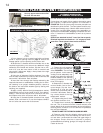
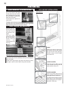
This application occurs when
venting through an exterior
wall. Having determined the air
terminal location, cut and frame
a hole in an exterior wall with a
minimum opening as required.
See Note above. (As an alterna-
tive to framing, a vent pipe shield
may be installed, ensuring a 1"
clearance to combustibles.
See Figure 16.)
1. Mark and cut the vent pipe
shield to the determined depth of the combustible wall.
Apply a bead of caulking (not supplied) to the framework or
to the shield plate (in the case of a finished wall) and se-
cure the shield through the opening to the interior wall. The
final location of the vent pipe shield should maintain the
required clearance to the 8" vent pipe / liner. (See note
above). Do not fill this cavity with any type of material. Ap-
ply a bead of caulking all around and place a firestop spacer
over the vent shield to restrict cold air from being drawn
into the room or around the fireplace. Ensure that both
spacer and shield maintain the required clearance to
combustibles. Once the vent pipe / liner is installed in its
final position, apply sealant between the pipe / liner and
the firestop spacer.
FIGURE 16
OR
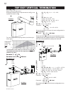
HORIZONTAL INSTALLATION
VERTICAL INSTALLATION
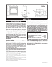
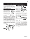
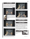
INSTALLATION
WALL AND CEILING PROTECTION
FIGURE 15
FIGURE 17