


Special offers from our partners!

Find Replacement BBQ Parts for 20,308 Models. Repair your BBQ today.

9
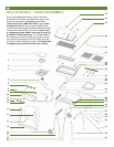
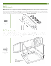
NOTE:
Threaded Insert on top
and nearest rear legs
NOTE:
notches closest
together to outside
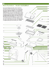
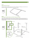
Rear Leg Assembly
Cylinder Support
Side Crossbrace
Right
Bowl Support
Left
Bowl Support
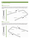
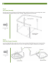
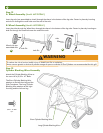
Step 3
Rear Crossbrace Assembly
Attach Rear Crossbrace inside Rear Leg Frame with 4) 1/4-20 x .39” Bolts. Note: The flanges on the ends of the cross-
brace tube are angled inward toward the top to match the angle of the legs.
1/4-20 x .39” Bolt
4 pc
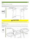
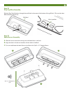
Step 4
Bowl Supports, Cylinder Support and Side Crossbrace Assembly
Attach the Left and Right Bowl Supports, Clyinder Support and Crossbrace to rear leg assembly with 8) 1/4-20 x .39”
Bolts. Note: Each part must be oriented as shown for proper assembly. Bolts should be snug but do NOT tighten com-
pletely at this stage. Note: The flanges on the ends of the crossbrace tube are angled inward toward the top to match
the angle of the legs.
1/4-20 x .39” Bolt
8 pc
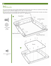
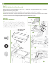
Rear Leg
Assembly
Holes in Bowl
Support align
with leg
Low side of raised area
to center
Rear Leg Assembly
Left Bowl Support
Holes are closest to
OUTSIDE edge