


Special offers from our partners!

Find Replacement BBQ Parts for 20,308 Models. Repair your BBQ today.
6
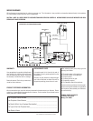
NOTE: DIAGRAMS & ILLUSTRATIONS NOT TO SCALE.
Sooting is indicated by black puffs developing
at the tips of very long orange flames. Sooting
results in black deposits forming on the logs,
appliance inside surfaces and on exterior sur-
faces adjacent to the face opening.
Sooting is caused by incomplete combustion in
the flames and a lack of combustion air entering
the air shutter opening. To achieve a warm yellow
to orange flame with an orange body that does
not soot, the shutter opening must be adjusted
between these two extremes.
These appliances should not smoke. Small
amounts of soot will accumulate over time
and should be expected. This soot adds to the
realism of the firebox interior. The logs can be
cleaned, when cool, with a soft brush and small
amounts of water.
If the logs are properly positioned and exces-
sive sooting conditions exist, the air shutter
opening on the main burner tube should be
adjusted. Keep in mind that this is an outdoor
appliance. Wind and air currents cannot be
strictly controlled.
If the flame acts too erratically, we recommend
that the screens be closed.
WARNING: AIR SHUTTER ADJUSTMENT
SHOULD ONLY BE PERFORMED BY A
QUALIFIED PROFESSIONAL SERVICE
TECHNICIAN.
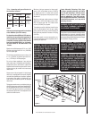
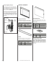
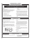
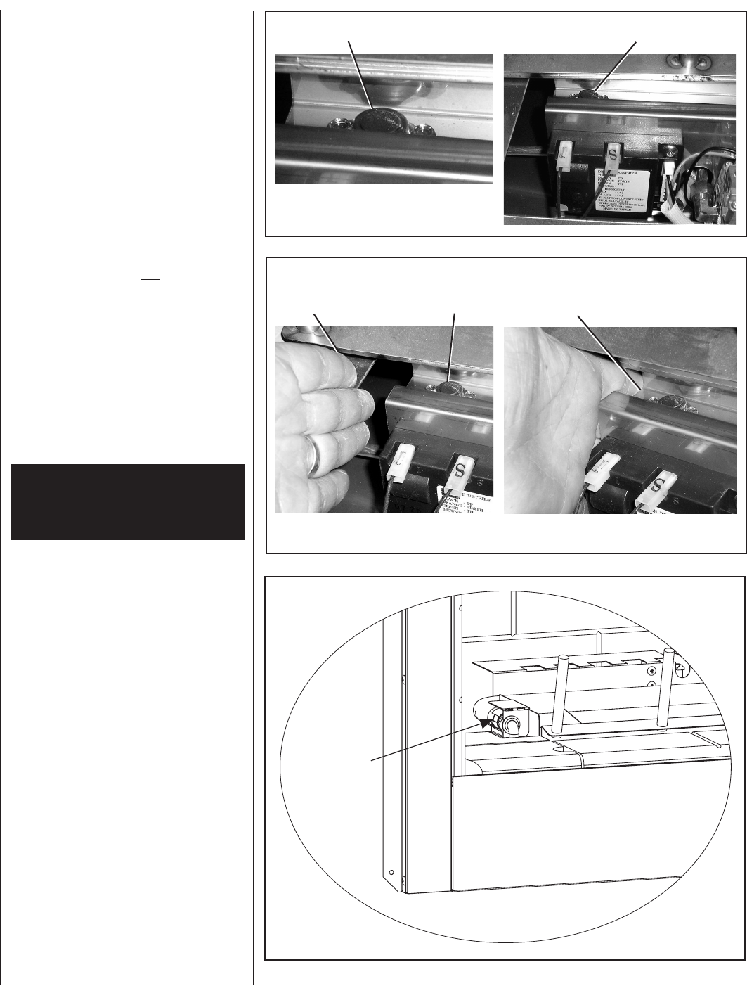
Shutter
Opening
1/16” For
Natural Gas
1/2” Open
For LP
Figure 6
Burner Adjustment
CAUTION: THE SHUTTER AND NEARBY APPLI-
ANCE SURFACES ARE HOT. EXERCISE CAU-
TION TO AVOID INJURY WHILE ADJUSTING
FLAME APPEARANCE.
To adjust the flame, turn the shutter (located
in the left side of the burner pan) up or down
to increase or reduce the air shutter opening,
respectively. Position the air shutter to the
factory setting, as shown in Figure 6.
Allow the burner to operate for at least 15
minutes. Observe the flame continuously. If it
appears weak or sooty as previously described,
adjust the air shutter by rotating the shuter until
the flame appearance is as desired.
When satisfied that the appliance operates
properly, proceed to finish the installation. Leave
the control knob in “ON” position and turn the
remote switch “OFF.” Reinstall the access and
refractory cover.
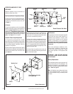
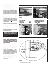
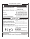
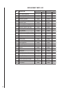
Figure 5
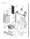
Figure 4
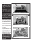
Limit Switch Detail
Limit Switch Location
Slide Left Hand
Underneath
Limit Switch
Limit
Switch
Use Middle Finger To Press
Reset Button On Underside
Of Limit Switch