


Special offers from our partners!

Find Replacement BBQ Parts for 20,308 Models. Repair your BBQ today.
NOTE: DIAGRAMS & ILLUSTRATIONS ARE NOT TO SCALE.
9
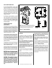
DETAILED INSTALLATION STEPS
The appliance is shipped with all gas controls
and components installed and pre-wired.
1. Remove the shipping carton, exposing the
front glass door.
2. Pull out the two spring loaded latches secur-
ing the glass door (located under the firebox
floor). Remove the door by tilting it outward
at the bottom and lifting it up and off. Set
the door aside protecting it from inadvertent
damage. See Figures 50 and 51 on Page
28.
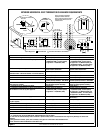
WARNING
Failure to position the parts in
accordance with these diagrams
or failure to use only parts specifi-
cally approved with this appliance
may result in property damage or
personal injury.
AVERTISSEMENT
Risque de dommages ou de
blessures si les pièces ne sont
pas installées conformément à
ces schémas et ou si des pièces
autres que celles spécifiquement
approuvées avec cet appareil sont
utilisées.
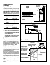
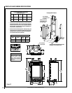
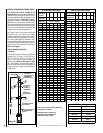
Step 1. FRAMING
Frame these appliances as illustrated in Figures
12 and 14 on Pages 10 and 12 (Figure 14
applies to corner framing installations only).
All framing details must allow for a minimum
clearance to combustible framing members as
shown in Table 5 on Page 8.
If the appliance is to be elevated above floor
level, a solid continuous platform must be
constructed below the appliance.
Headers may be in direct contact with the
appliance top spacers but must not be sup-
ported by them or notched to fit around them.
All construction above the appliance must be
self-supporting, DO NOT use the appliance for
structural support.
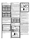
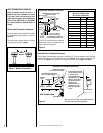
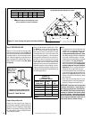
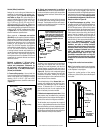
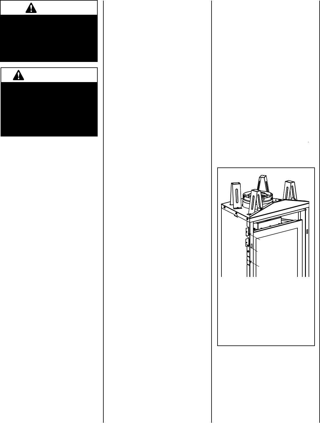
The fireplace should be secured to the side fram-
ing members using the unit's nailing flanges
on
each side of the fireplace front (see Figure 11).
Use 8d nails or their equivalent.
Figure 11
Left Side Front Corner of Fireplace Shown
(Right Side Requirements the Same)
Unit Being Secured By Its Nailing
Flanges To The Framing
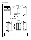
Frame the opening to the exact dimensions
specified in the framing details in this manual.
Use Top Flange For
5/8” Thick Drywall
Use Center Flange For
1/2” Thick Drywall
Use Bottom Flange
For Flush Mount
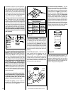
TYPICAL INSTALLATION SEQUENCE
The typical sequence of installation is outlined
below. However, each installation is unique
and may result in variations to the steps
described.
See the page numbers references in the follow-
ing steps for detailed procedures.
Step 1. (Page 9) Construct the appliance
framing. Position the appliance within
the framing and secure with nailing
brackets.
Step 2. (Page 12) Route gas supply line to
appliance location.
Step 3. (Page 13) Install the vent system and
exterior termination.
Step 4. (Page 23) Field Wiring
.25 a. Millivolt Appliances – The operating
control switch is factory installed.
.25 b. Electronic Appliances – Connect 120
Vac electrical power to the appliance
receptacle.
Step 5. (Page 24) Install blower kit (optional
equipment).
Step 6. (Page 24) Make connection to gas
supply.
Step 7. (Page 25) Verify appliance opera-
tion.
BEFORE PROCEEDING TO STEP 8, INSTALL
A FIREBOX LINER KIT PER INSTRUCTIONS
PROVIDED IN THE KIT (REQUIRED - SOLD
SEPARATELY).
Step 8. (Page 26) Install the logs and glowing
embers.
Step 9. (Page 28) Install glass door assem-
bly.
Step 10. (Page 29) Adjust burner to ensure
proper flame appearance.
Step 11. (Page 31) Attach Safety in Operation
Warnings.