


Special offers from our partners!

Find Replacement BBQ Parts for 20,308 Models. Repair your BBQ today.

9
10
464224011 • 19
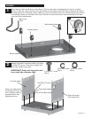
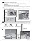
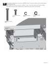
Insert front brace under control panel and between cart side panels. Secure using two 1/4-20x1¾” screws,
Under front brace, secure cart partition panel to front brace using one #8-3/8” tapping screw, shown B.
7mm lock washers and 7mm flat washers on each side, shown A.
7mm lock
7mm Lock washer
Front brace
Control panel
Washer
7mm flat
Washer
Screw
1/4-20x1¾”screw
Qty.4
Qty.4
A
B
Cart partition panel
Front brace
#8-3/8” tapping screw
#8-3/8” tapping screw
Qty.1
Qty.4
7mm flat washer
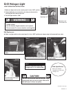
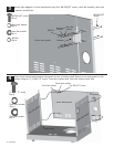
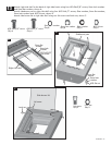
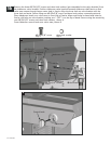
Connect each of the ignition wires from the main burner electrodes and sideburner electrode into the
Untie the 7 burner ignition wires bundled under the right side of grill head. Draw the wires over the cart
back of the Electronic Ignition Module. Total (7) connections.
from the switch wiring harness into the back of the Electronic Ignition Module. Total (2) connections.
Untie the two wires [(a) and (b)] from under the left side of grill head. Connect the two wires [(a) and (b)]
NOTE: Switch terminals are larger than electrode terminals and should only be installed in locations shown as
ignition module
Electronic
Heat shield
Left side panel
A
B
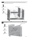
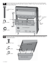
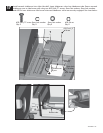
Remove the cap and nut from electronic ignition module. Attach electronic ignition module and heat
shield to cart left side panel with the nut, shown A.
Insert AA battery into ignition module, negative (-) end first. Then put on the cap, shown B.
Nut
-
+
AA batteryCap
4
1
2
3
6
7
5
(a)
(b)
.
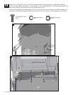
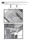
Use one of the bundling ties to bundle the 9 wires together, and tie to the gas line hose so that the
wires don't hang down into the cabinet.
partition panel.
(a),(b).
1/4-20x1¾”