


Special offers from our partners!

Find Replacement BBQ Parts for 20,308 Models. Repair your BBQ today.
28
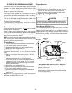
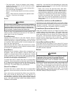
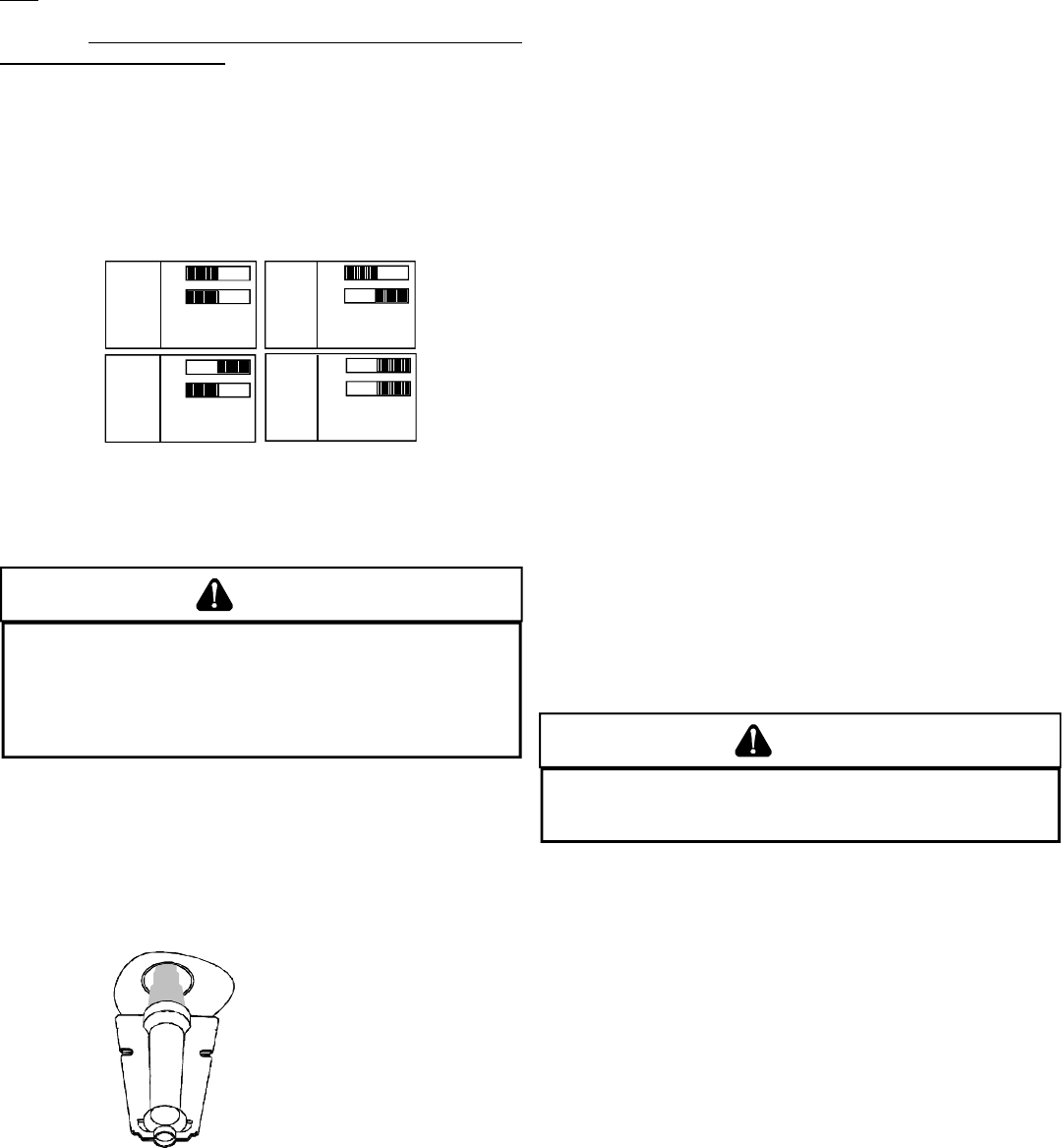
CIRCULATOR B LOWER FAN TIMING A DJUSTMENT
NOTE: Items in this section refer to the air circulator blower fan,
NOT to the induced draft blower. The induced draft blower timing
sequence is not adjustable. The circulator blower fan timing is
adjustable
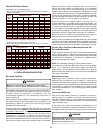
only on models with optional “heating fan OFF delay”
adjustment pins or switches (Figure 28). It is NOT adjustable in
any other circumstances.
As shipped, the circulator blower fan will remain on for 150
seconds after the gas valve closes. The circulator blower then
ramps down to “OFF” during the 30 seconds following the heat off
delay period. When a call for cooling occurs, the circulator fan
comes on and remains on for 45 seconds after the call for cooling
ends. During normal heating operation, the circulator fan will come
on approximately 34 seconds after the gas valve opens.
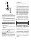
O
N
O
F
F
O
N
O
F
F
O
N
O
F
F
O
N
O
F
F
1 2
1 2
1 2
1 2
90
SECOND
DELAY
120
SECOND
DELAY
150
SECOND
DELAY
180
SECOND
DELAY
Switches viewed in an upflow installation.
Adjustment Switches
XIII. OPERATIONAL CHECKS
WARNING
T
O AVOID PERSONAL INJURY OR DEATH, DO NOT REMOVE ANY INTERNAL
COMPARTMENT COVERS OR ATTEMPT ANY ADJUSTMENT.
E
LECTRICAL
COMPONENTS ARE CONTAINED IN BOTH COMPARTMENTS.
T
O PREVENT
PROPERTY DAMAGE, PERSONAL INJURY OR DEATH DUE TO EXPLOSION
AND/OR FIRE, CONTACT A QUALIFIED SERVICE AGENT AT ONCE IF AN
ABNORMAL FLAME APPEARS.
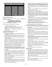
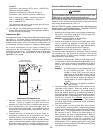
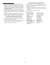
BURNER FLAME
The burner flames should be inspected with the burner
compartment door installed. Flames should be stable, quiet,
soft, and blue (dust may cause orange tips but they must not be
yellow). Flames should extend directly outward from the burners
without curling, floating, or lifting off. Flames must not impinge on
the sides of the heat exchanger firing tubes.
Check the burner flames for:
1. Good adjustment
2. Stable, soft and blue
3. Not curling, floating, or lifting off.
Burner Flame
AUXILIARY L IMIT C ONTROL
A uto reset limits are located on or near the blower. To access this
auxiliary limit, disconnect the electrical power and remove the
blower door. If the limit control opens, the air circulation blower
will run continuously. The diagnostic light will flash one time. The
auxiliary limit control is designed to prevent furnace operation in
case of main blower failure on horizontal and counterflow
installations. It may also open if the power supply is interrupted
while the furnace is firing. The auxiliary limit control is suitable for
both horizontal right and horizontal left installations. Regardless
of airflow direction, it does not need to be relocated.
PRIMARY LIMIT
The primary limit control guards against overheating resulting
from insufficient conditioned air passing over the heat exchanger.
If the primary limit control does not function during this test, the
cause must be determined and corrected. Function of this control
should be verified by gradually blocking the furnace return air after
the furnace has been operating (burners firing) for approximately
ten minutes. Check the control as follows:
1. Allow the furnace to operate with burners firing continuously
for approximately ten minutes.
2. Gradually block the return air to furnace. Remove airflow
blockage when limit control is activated and turns off
burners. Airflow blockage causes unit overheating and
will produce the following reactions:
• The gas valve to close and extinguish flame,
• The induced draft blower to be de-energized after a fifteen
second postpurge, and
• The circulator blower to remain energized continuously until
limit control resets.
3. Remove the return air blockage to clear overheating
condition. After an acceptable temperature is reached
during the cool down period, the limit control will reset and
allow the furnace to resume normal operation.
WARNING
T
O PREVENT PREMATURE FAILURE OF HEAT EXCHANGER, PROPERTY DAMAGE,
PERSONAL INJURY OR DEATH, DO NOT ADJUST THE LIMIT CONTROL (FACTORY
SET).
XIII. SAFETY CIRCUIT DESCRIPTION
IMPORTANT NOTE: This unit must not be used as a construction
heater during the finishing phases of construction of a new
structure. This type of use may result in premature failure due to
extremely low return air temperatures and exposure to corrosive
or very dirty atmospheres.
These checks establish that the primoary limit control is functioning
and will respond to a restriction in the return air, or a circulator
blower failure. If the primary limit control does not function during
this test, the cause must be determined and corrected.
GENERAL
A number of safety circuits are employed to ensure safe and proper
furnace operation. These circuits serve to control any potential
safety hazards and serve as inputs in the monitoring and diagnosis
of abnormal function. These circuits are continuously monitored
during furnace operation by the integrated control module.