


Special offers from our partners!

Find Replacement BBQ Parts for 20,308 Models. Repair your BBQ today.
22
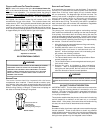
When the furnace is used in connection with a cooling unit, the
furnace should be installed in parallel with or on the upstream
side of the cooling unit to avoid condensation in the heating
element. With a parallel flow arrangement, the dampers or other
means used to control the flow of air must be adequate to prevent
chilled air from entering the furnace and, if manually operated,
must be equipped with means to prevent operation of either unit
unless the damper is in the full heat or cool position.
When the furnace is installed without a cooling coil, it is
recommended that a removable access panel be provided in the
outlet air duct. This opening shall be accessible when the furnace
is installed and shall be of such a size that the heat exchanger
can be viewed for visual light inspection or such that a sampling
probe can be inserted into the airstream. The access panel must
be made to prevent air leaks when the furnace is in operation.
When the furnace is heating, the temperature of the return air
entering the furnace must be between 55°F and 100°F.
When a furnace is installed so that supply ducts carry air circulated
by the furnace to areas outside the space containing the furnace,
the return air shall also be handled by a duct sealed to the furnace
casing and terminating outside the space containing the furnace.
FILTERS - READ THIS SECTION BEFORE INSTALLING THE
RETURN A IR D UCTWORK
Filters must be used with this furnace. Discuss filter maintenance
with the building owner. Filters do not ship with this furnace, but
must be provided by the installer. Filters must comply with UL900
or CAN/ULCS111 standards. If the furnace is installed without
filters, the warranty will be voided.
NOTE: An undersized opening will cause reduced airflow.
For air delivery of less than 1800 CFM, use a one side or bottom
return. For air delivery of 1800 CFM or higher, use either two-
sided returns or a one-sided return with a bottom return. Refer to
Minimum Filter Area tables at the end of this manual to determine
filter area requirements.
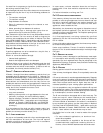
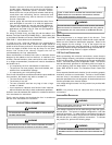
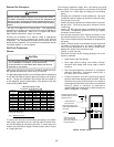
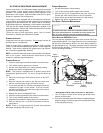
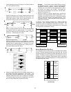
UPRIGHT I NSTALLATIONS
Depending on the installation and/or customer preference,
differing filter arrangements can be applied. Filters can be
installed in the central return register or a side panel external filter
rack kit (upflows), or the ductwork above a counterflow furnace. As
an alternative, a media air filter or electronic air cleaner can be
used as the requested filter. The following figures show possible
filter locations.
CIRCULATION A IR F ILTERS
One of the most common causes of a problem in a forced air
heating system is a blocked or dirty filter. Circulating air filters
must be inspected monthly for dirt accumulation and replaced if
necessary. Failure to maintain clean filters can cause premature
heat exchanger failure.
A new home may require more frequent replacement until all
construction dust and dirt is removed. Circulating air filters are to
be installed in the return air duct external to the furnace cabinet.
WARNING
B
EFORE PERFORMING ANY SERVICE ON THIS FURANCE, DISCONNECT THE
MAIN POWER SUPPLY.
D
O NOT OPERATE THE FURNACE WITHOUT
CIRCULATIONG AIR FILTERS IN PLACE.
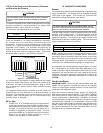
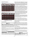
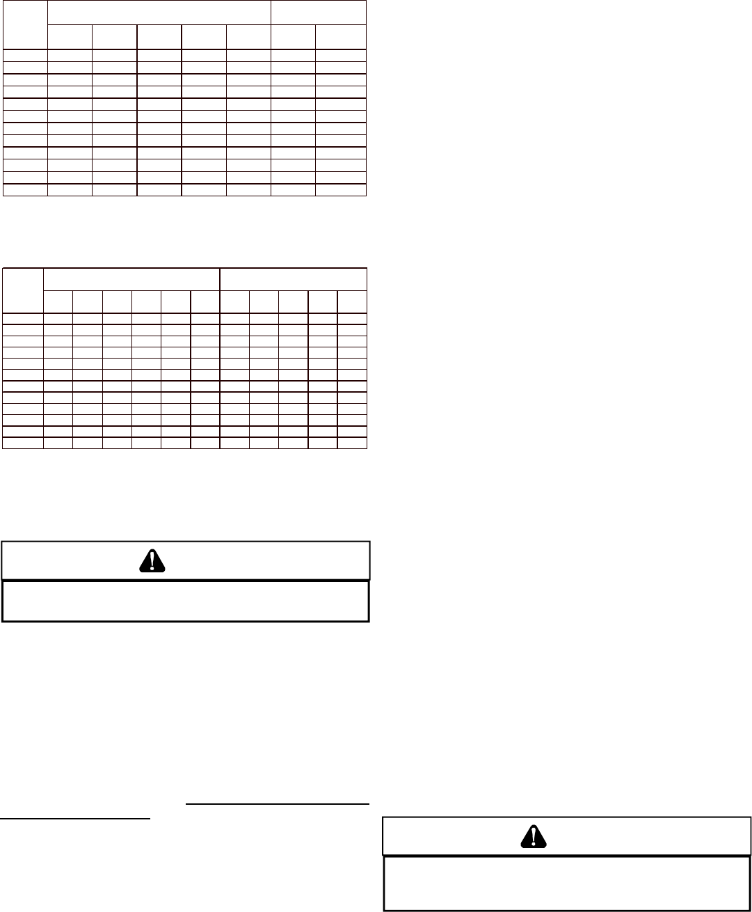
PROPANE GAS PIPING CHARTS
Sizing Between First and Second Stage Regulator*
Maximum Propane Capacities listed are based on 2 psig pressure drop at 10 psig setting.
Capacities in 1,000 BTU/hour.
Pipe or Nominal Pipe Size
Tubing Tubing Size, O.D. Type L Schedule 40
Length, 3/8
"
1/2
"
5/8
"
3/4
"
7/8
"
1/2
"
3/4
"
Feet
10 730 1,700 3,200 5,300 8,300 3,200 7,500
20 500 1,100 2,200 3,700 5,800 2,200 4,200
30 400 920 2,000 2,900 4,700 1,800 4,000
40 370 850 1,700 2,700 4,100 1,600 3,700
50 330 770 1,500 2,400 3,700 1,500 3,400
60 300 700 1,300 2,200 3,300 1,300 3,100
80 260 610 1,200 1,900 2,900 1,200 2,600
100 220 540 1,000 1,700 2,600 1,000 2,300
125 200 490 900 1,400 2,300 900 2,100
150 190 430 830 1,300 2,100 830 1,900
175 170 400 780 1,200 1,900 770 1,700
200 160 380 730 1,100 1,800 720 1,500
To convert to capacities at 15 psig settings - multiply by 1.130
To convert to capacities at 5 psig settings - multiply by 0.879
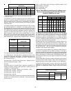
Sizing Between Single or Second Stage Regulator and Appliance*
Maximum Propane Capacities Listed are Based on 1/2" W.C. pressure drop at 11" W.C. setting.
Capacities in 1,000 BTU/hour.
Pipe or Nominal Pipe Size
Tubing Tubing Size, O.D. Type L Schedule 40
Length, 3/8" 1/2" 5/8
"
3/4" 7/8" 1-1/8" 1/2" 3/4" 1
"
1-1/4
"
1-1/2"
Feet
10 39 92 199 329 501 935 275 567 1,071 2,205 3,307
20 26 62 131 216 346 630 189 393 732 1,496 2,299
30 21 50 107 181 277 500 152 315 590 1,212 1,858
40 19 41 90 145 233 427 129 267 504 1,039 1,559
50 18 37 79 131 198 376 114 237 448 913 1,417
60 16 35 72 121 187 340 103 217 409 834 1,275
80 13 29 62 104 155 289 89 185 346 724 1,066
100 11 26 55 90 138 255 78 162 307 630 976
125 10 24 48 81 122 224 69 146 275 567 866
150 9 21 43 72 109 202 63 132 252 511 787
200 8 19 39 66 100 187 54 112 209 439 665
250 8 17 36 60 93 172 48 100 185 390 590
*Data in accordance with NFPA pamphlet NO. 54
X. CIRCULATING AIR AND FILTERS
DUCTWORK - AIR FLOW
WARNING
NEVER ALLOW THE PRODUCTS OF COMBUSTION, INCLUDING CARBON
MONOXIDE, TO ENTER THE RETURN DUCTWORK OR CIRCULATION AIR SUPPLY.
Duct systems and register sizes must be properly designed for
the CFM and external static pressure rating of the furnace.
Ductwork should be designed in accordance with the
recommended methods of “Air Conditioning Contractors of
America” Manual D.
A duct system must be installed in accordance with Standards of
the National Board of Fire Underwriters for the Installation of Air
Conditioning, Warm Air Heating and Ventilating Systems.
Pamphlets No. 90A and 90B.
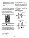
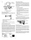
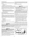
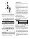
A closed return duct system must be used, with the return duct
connected to the furnace. NOTE:
Ductwork must never be attached
to the back of the furnace. Supply and return connections to the
furnace may be made with flexible joints to reduce noise
transmission. To prevent the blower from interfering with
combustion air or draft when a central return is used, a connecting
duct must be installed between the unit and the utility room wall. A
room, closet, or alcove must not be used as a return air chamber.