


Special offers from our partners!

Find Replacement BBQ Parts for 20,308 Models. Repair your BBQ today.
10 4039-150 Rev B 01/04
MONTANA INSTALLATION INSTRUCTIONS
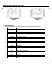
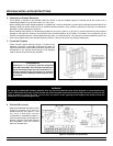
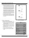
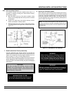
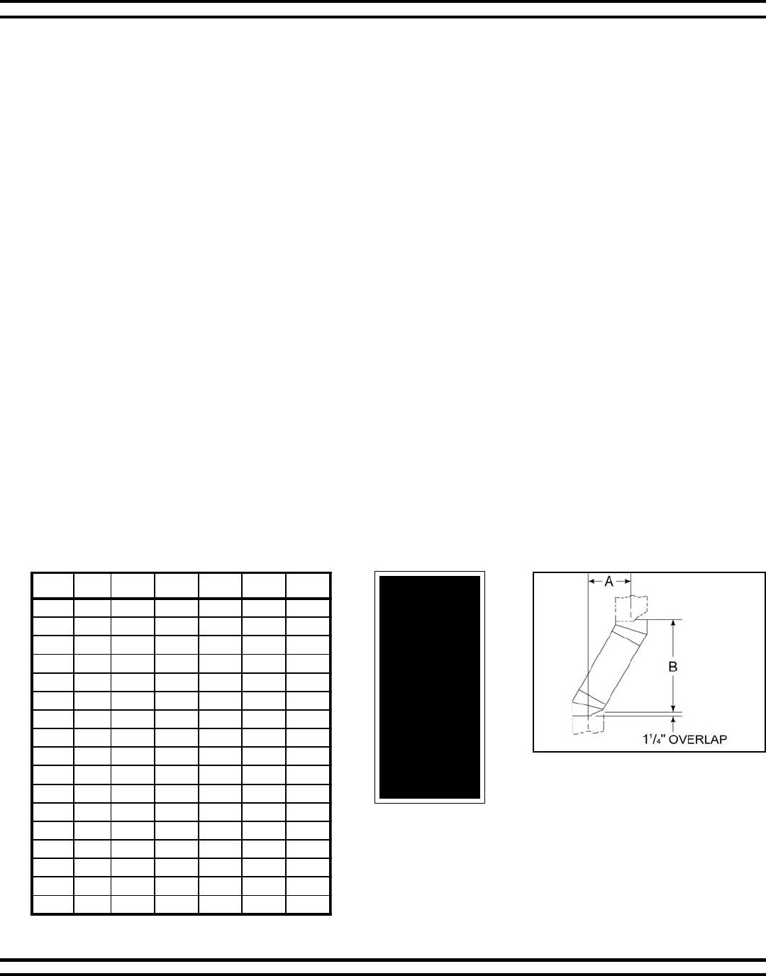
Figure 7 - Chimney Offset/Return
Example: Your A dimension from
Figure 7 is 14½. Using Table 1 the
dimension closest to, but not less than
14½ is 14
5
/8 using a 30° offset/return.
It is then determined from the table that
you would need 33 (Dimension B)
between the offset and return. The
chimney components that best fit your
application are two SL1112s.
WARNING!
Do not com-
bine offsets to
create an off-
set greater
than 30° from
vertical. This
may create a
fire hazard
since the natu-
ral draft may
be restricted.
AB 6011LS2111LS8111LS6311LS8411LS
3
7
/
8
""½41 -----
"¼681
5
/
8
"1----
"¼9"¾32 -1---
"¼21"92--1--
41
5
/
8
""33-2---
71
5
/
8
""¼83 - 11- -
"¼1244
5
/
8
"---1-
32
5
/
8
""¾84 1--1-
"¼72"¾55 ----1
92
5
/
8
""951---1
23
5
/
8
""¼46 -1--1
53
5
/
8
""½96 --1-1
"8337
5
/
8
"-2--1
"14"¾87 - 11- 1
44
5
/
8
""58---11
"7498
1
/
8
"1--11
05
5
/
8
""½59 ----2
nanistluserstrapyenmihcdeloocriafoylbmessareporP
otnitliubsihtgnelevitceffE."¼1fostniojyenmihctapalrevo
.elbatsiht
Offset/Returns Table 1
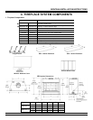
1. Using Offsets and Returns
a. To bypass any overhead obstructions, the chimney may be offset using a 30° offset/return (SL1130). Perform the following
steps to determine the correct chimney component combination for your particular installation.
b. An offset and return may be attached together or a chimney section(s) may be used between an offset and return.
1) Measure how far the chimney needs to be shifted to enable it to avoid the overhead obstacle. See Figure 7, dimension A
to determine chimney sections required to achieve the needed shift.
2) After determining the offset dimension, refer to Table 1 and find the A dimension closest to but not less than the
distance of shift needed for your installation.
3) The B dimension that coincides with the A dimension represents the required vertical clearance that is needed to
complete the offset and return.
4) Read across the chart and find the number of chimney sections required and the model number of those particular
chimney parts.
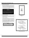
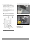
5) Whenever the chimney penetrates a floor/ceiling, a firestop spacer must be installed.
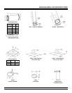
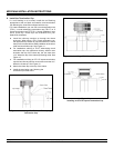
6) The effective height of the fireplace assembly is measured from the base of fireplace to top of starter collar. See Figure 6.
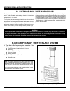
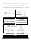
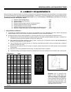
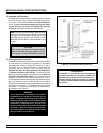
E. CHIMNEY REQUIREMENTS
When planning your fireplace location, the chimney construction and necessary clearances must be considered. The fireplace system
and chimney components have been tested to provide flexibility in construction. The following figures are the minimum distances from
the base of the fireplace. Minimum overall straight height is 6 4 if the fireplace is freestanding a minimum of 10 from a
combustible structure. See Figure 2, page 8.
1. Minimum overall straight height 14 ft.
2. Minimum height with offset/return 16 ft.
3. Maximum height 90 ft.
4. Maximum chimney length between an offset and return 20 ft.
5. Maximum distance between chimney stabilizers 35 ft.
6. Double offset/return minimum height 24 ft.
7. Maximum unsupported chimney length between the offset and return 6 ft.
8. Maximum straight unsupported chimney height above the fireplace 35 ft.