


Special offers from our partners!

Find Replacement BBQ Parts for 20,308 Models. Repair your BBQ today.
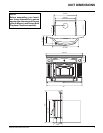
Hampton HI300 Wood Cast Insert 7
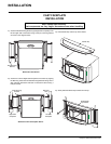
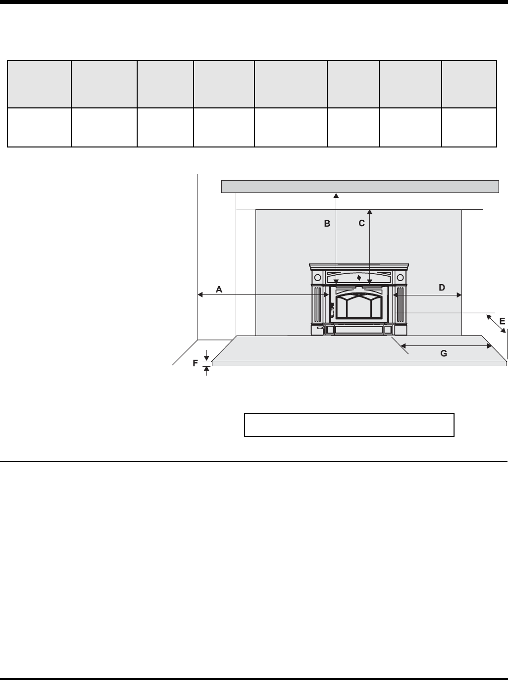
Clearance Diagram for Installations
Side and Top facing is a maximum of 1.5" thick.
Floor protection must be non-combustible, insula-
tive material with an R value of 1.1 or greater.
* Hearth thickness of 0.5" with k value = 0.84",
R value = 0.6 or greater.
Thermal fl oor protection not required if unit is
raised 3.5" min. measured from bottom of stove. At
this point the standard ember fl oor protection will
be required. It will need to be a non-combustible
material that covers 16" (406 mm) to the front
of the unit (in Canada 18" (450 mm) and 8" (200
mm) to the sides.
All fl oor protection must be non-combustible (i.e.,
metals, brick, stone, mineral fi ber boards, etc.) Any
organic materials (i.e. plastics, wood paper prod-
ucts, etc.) are combustible and must not be used.
The fl oor protection specifi ed includes some form
of thermal designation such as R-value (thermal
resistance) or k-factor (thermal conductivity).
** A non-combustible mantel may be installed
at a lower height if the framing is made of
metal studs covered with a non-combustible
board.
** Max. mantle depth is 10" (254mm)
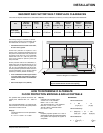
MASONRY AND FACTORY BUILT FIREPLACE CLEARANCES
The minimum required clearances to combustible materials when installed into a masonry or factory built fi replace are listed below.
Adjacent Mantle** Top Side Minimum Minimum Minimum
Unit Side Wall (to Top) Facing Facing Hearth Hearth Hearth Side
(to Side of unit) (to Top) (to Side of unit) Extension* Thickness* Extension
A B C D E F G
Wood Cast
Insert (HI300) 11"/280mm 20"/508mm 12"/305mm 8"/200mm 18"/455mm 0.5"/13mm 8"/200mm
Minimum Hearth Extension for the front (E) and sides
(G) are measured from the fuel door opening.
HOW TO DETERMINE IF ALTERNATE
FLOOR PROTECTION MATERIALS ARE ACCEPTABLE
The specifi ed fl oor protector should be 3/8"
(18mm) thick material with a K - factor of
0.84.
The proposed alternative is 4" (100mm) brick
with a C-factor of 1.25 over 1/8" (3mm) mineral
board with a K-factor of 0.29.
Step (a):
Use formula above to convert specifi cation
to R-value.
R = 1/k x T = 1/0.84 x .75 = 0.893.
Step (b):
Calculate R of proposed system.
4" brick of C = 1.25, therefore
Rbrick = 1/C = 1/1.25 = 0.80
1/8" mineral board of k = 0.29, therefore
Rmin.bd. = 1/0.29 x 0.125 = 0.431
Total R = Rbrick + Rmineral board =
0.8 + 0.431 = 1.231.
Step (c):
Compare proposed system R of 1.231 to
specifi ed R of 0.893. Since proposed system
R is greater than required, the system is
acceptable.
DEFINITIONS
Thermal Conductance:
C = Btu = W
(hr)(ft
2
)(
o
F) (m
2)
)(K)
Thermal Conductivity:
k = (Btu)(inch) = W = Btu
(hr)(ft
3
)(
o
F) (m)(K) (hr)(ft)(
o
F)
Thermal Resistance:
R = (ft
2
)(hr)(
o
F) = (m
2
)(K)
Btu W
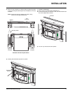
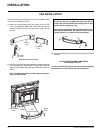
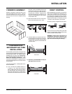
INSTALLATION