


Special offers from our partners!

Find Replacement BBQ Parts for 20,308 Models. Repair your BBQ today.

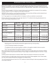
BURNER SYSTEM INSTALLATION
Model GB-TFII-18 GB-TFII-18 GB-TFII-24/30 GB-TFII-24/30
Gas Type Natural L.P. Natural L.P.
Max Input 30,000btu/hr 30,000btu/hr 38,000btu/hr 35,000btu/hr
Min Input 19,000btu/hr 26,000btu/hr 22,700but/hr 28,500btu/hr
Gas Inlet Pressure
Maximum 10.5 IN. wc 14.0 IN. WC 10.5 IN. WC 14.0 IN. WC
Minimum 5.0 IN. WC 11.0 IN. WC 5.0 IN. WC 11.0 IN. WC
Regulator Pressure 3.5 IN. WC 10.0 IN. WC 3.5 IN. WC 10.0 IN. WC
Before starting installation, find out if local and state codes approve vent-free gas logs. If unvented gas logs are not
approved, the installation must be made with the fireplace damper partially open and locked to assure the minimum
vent area required by local codes or the National Gas Fuel Code (ANSI Z223.1-latest edition). Use the damper clamp
provided.
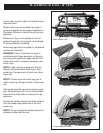
Clean the firebox thoroughly. In the future, frequent cleaning may be required due to excessive lint from carpeting
and other materials. All burner components must always be kept clean.
WARNING: Before installing in a solid fuel burning fireplace, the chimney flue and firebox must be cleaned of soot,
creosote, ashes and loose paint by qualified chimney cleaner.
If a 1/2“ gas supply line is not already installed in the fireplace, a call to your plumber is recommended.
Check to make sure the gas supply is the same type (natural or L.P.) as listed on the rating plate attached to the
burner. Note the approved gas pressure chart.
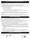
Manifold pressure check should be made with the appliance burning in the high setting.
A 1/8“ NPT test plug is located on the regulator.
LP Installations require an external regulator in addition to the regulator installed in the burner system.
The LP tank could explode if the additional regulator is not installed.
When checking gas inlet pressure, the appliance must be isolated from the gas supply line by closing its individual
manual shut off valve during and pressure testing of the gas supply at test pressures equal to or less then 1/2 psig.
(3.5 KPA)
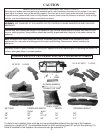
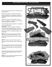
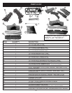
Centrally locate the burner/grate unit inside the firebox. Position burner/grate unit towards rear of the firebox.
Connect the burner to the gas supply using the connector tube and brass elbow supplied in the kit. Some installa-
tions may require different fittings that are available from hardware stores.
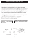
Turn on the gas with the burner valve in the “OFF” position and check all fittings for leaks using soapy water. Do not
use a flame to leak test.
4