


Special offers from our partners!

Find Replacement BBQ Parts for 20,308 Models. Repair your BBQ today.

4
EXHAUST REMOVAL
If installed under a patio roof, the cooking grid area
should be fully covered by a chimney and exhaust hood.
An exhaust fan with a rating of at least 1000 CFM may
be necessary to efficiently remove smoke and other
cooking by-products from the covered area.
Installation in fully-enclosed patio areas is not
recommended.
GAS SUPPLY PLUMBING REQUIREMENTS:
Rigid ½" black steel pipe is required to conduct the gas
supply into the barbecue enclosure for connection to
the unit. Pipe joint compound which is resistant to all
gases should be applied to all male fittings and all joints
tightened securely. Do not use pipe joint compound to
connect flare fittings.
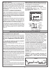
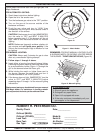
The pipe should terminate near the front and center of
the enclosure, no more than 5" from the counter top.
Installation will be simplified if the pipe enters the
enclosure vertically from the bottom, at least 6" in from
each side and within 8" of the front wall (Figure 1).
If the pipe does not come up against the front wall, it
can easily be run along the enclosure floor and turned
up to rise within 5" of the counter top, tight against the
front wall (leaving space only to connect fittings,
Figure 2).
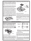
Perform the following checks before installing your barbecue:
CHECK BARBECUE FUEL ORIFICE SIZE
Fire Magic Barbecues are equipped with orifices for natural
gas unless otherwise indicated. For use with propane gas,
smaller orifices must be installed to avoid hazardous
overheating. The orifice size for Natural Gas is #47 (drill
size) and for Propane Gas, the orifice size is #55 (drill
size).
IF YOU ARE NOT SURE YOU HAVE THE CORRECT
BARBECUE BURNER ORIFICE SIZE
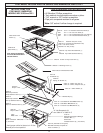
a. Remove the cooking grids and flavor grid from your
barbecue.
b. If the gas supply has been connected, make sure the
burner valve is in the 'OFF' position. Then pull the knobs
from their stems. Use a phillips screwdriver to turn the face
fastener screws counterclockwise to release the face and
remove it from the barbecue. Make sure to retain the screws
and finish washers until you are ready to reattach the face.
Note: Carefully lift the face away from the frame. The spark
generators for the ignition system are attached to the
inside of the face panel. The spark generator need not be
detached, but the wires must be unplugged from the
generators before the face is removed.
c. Using a flat blade screwdriver, pry the burner retaining
clip from rear wall of the barbecue frame (see Figure 3).
Remove the burner by; 1) Pulling it to the front of the
barbecue, 2) Lift the far end out of the notch, 3) Pull the
burner away from the manifold, taking care not to lose air
shutter and spring, which may become detached when the
burner is removed.
d. Using a 3/8" socket, remove orifice from the orifice holder
on the burner manifold and check the number stamped on
the face (see barbecue fuel orifice size above). Repeat for
each burner as necessary.
e. If your barbecue is not orificed for the gas supply you
plan to use, replace them with the orifices supplied with
the barbecue or orifices supplied by your local dealer.
f. After checking orifice drill size or replacing the orifice,
install the air shutter spring and the air shutter over the
orifice holder fitting, between the burner and the burner
manifold, in the order and position shown in Figure 3.
g. Replace the burners in the holding groove, ensuring that
the brass orifice and orifice holder fittings project deeply
into the burners. Replace the burner retaining clips.
CONNECT THE GAS SUPPLY TO BARBECUE
a. You will need a C.S.A. approved stainless steel flex
connector to bring the gas supply from the gas line stub to
the valve manifold. A 1/2" x 24" flex stainless steel
connector is suitable for most installations. A 1/2" female
flare fitting is required to connect to the unit. Only listed
stainless steel connectors should be used to connect the
barbecue to the gas line inside the enclosure.
CAUTION: Use only stainless steel flex connectors that
are C.S.A. listed.
WARNING: A rubber or plastic connector will
rupture or leak, resulting in an explosion or
serious injury if used inside the barbecue
enclosure.
STUB OUT GAS PIPE
ANYWHERE IN THIS AREA
VERTICAL PIPE
UP AGAINST FRONT
BACK
24 1/4"
19 1/4"
6"
12"
6"
Figure 1 - Top View
Figure 2 - View from Left
REAR
COUNTER TOP
FRONT
9" MIN.
5" MAX.
12 MIN.
8" MAX.
SAFETY NOTE: An external valve in the gas line is
necessary for safety when your barbecue is not in use.
It also provides for convenient maintenance and repair.
A removable key is recommended.
GAS SUPPLY AND MANIFOLD PRESSURE:
For Natural Gas - Normal 7" w.c. (Water Column),
Minimum 3 1/2", Maximum 10 1/2"
For Propane Gas - Normal 11" w.c., Minimum 8",
Maximum 13"
INSTALLING YOUR FIRE MAGIC DELUXE DROP-IN BARBECUE
AIR SHUTTER
BURNER
MANIFOLD WITH
ORIFICE HOLDER
BURNER
ORIFICE
SPRING
BURNER NECK
BURNER CLIP
Figure 3