


Special offers from our partners!

Find Replacement BBQ Parts for 20,308 Models. Repair your BBQ today.

6
BARBECUE SAFETY INFORMATION & MAINTENANCE
Each time you use your barbecue, make sure that:
1. The area around the barbecue is clear of flammable substances such
as gasoline, yard debris, wood, etc.
2. There is no blockage of the air flow through the vent space located
below the face of the unit.
3. When using propane gas:
a. The special ventilation openings in the enclosure are kept free
and clear of debris.
b. If connected to a propane cylinder, the rubber hose attached to the
regulator is carefully inspected before each use.
c. The propane cylinder, regulator and rubber hose are installed in a
location not subject to heating above 125° F (51° C).
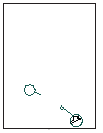
Figure 6
CHECKING AND ADJUSTING YOUR BARBECUE (CONTINUED)
REATTACHING THE FACE & IGNITOR WIRES
Pull the drip tray out far enough to support the face in the
vertical position. Lean the face forward and plug the ignitor
wires into the spark generator.
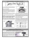
The large knobs on the face of the barbecue control the valves
and adjust flame height. The first position is ‘HIGH’, the second
‘MEDIUM’ and final ‘LOW’. Flame height can be set anywhere
between ‘HIGh’, ‘MEDIUM’ and ‘LOW’ settings for all cooking
requirements and methods.
Height of flame with the
valve in low position
may be
regulated by means of a small adjusting screw in center of
valve stem. This screw is accessible by removing the plastic
valve knob which pulls straight off the valve stem.
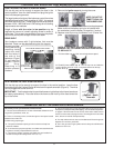
RIGID SHELF
Your barbecue comes with 2 rigid shelves, that must be
attached. These can be attached using the four support
screws provided.
Line up the four (4)
mounting holes
inside the shelf
with the holes in
the side of the
barbecue (Figure
8), and insert the
screws.Tighten
until snug.
Detaching is a
reverse process
of above.
AIR SHUTTER
ACCESS PANEL
SHELF SUPPORT
SCREWS
VIEW FROM UNDER RIGHT SHELF
Figure 8
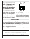
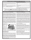
REPLACING THE SPARK GENERATOR BATTERY
1. Remove the ignitor cover by turning the cover
counterclockwise and lifting it away.
2. The battery is now accessible for removal and replacement.
Make sure that the battery spring is re-installed with
the new battery, and the battery is negative (-) end up.
3. Replace cover by turning it clockwise until it locks into
place
RIGHT!
WRONG!
NOTE: DO NOT AT-
TEMPT TO PULL ON
THE RUBBER CAP.
*NOTE: IF YOU HAVE ACCIDENTLY REMOVED THE
RUBBER CAP, FOLLOWING INSTRUCTIONS BELOW
TO REPLACE IT.
1. Pull the rubber cap and the inner plastic sleeve apart.
3. Turn the cap over and slide the
inner plastic sleeve into the cap.
2. Carefully insert rubber cap
into the ignitor cover so it sits
behind inner lip.
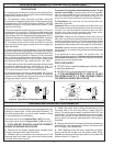
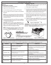
REATTACHING THE FACE & IGNITOR WIRES
Pull the drip tray out far enough to support the face in the vertical position. Lean the face
forward and plug the 2 wires into the terminals on the spark senerator (Figure 9). The wires
can be plugged into either terminal.
IMPORTANT: Test the electrodes for spark before securing the face to the frame (see above
for battery replacement). Place the face on the frame so the front lip of the face covers the
lip on the frame.
Figure 9 - Spark
Generator
4. The burner flames burn evenly along both sides of each burner with a
steady flame (mostly blue with yellow tipping). See “Air Shutter Adjustment”
on page 5. If burner flames are not normal, check orifice and burner for
insects or insect nests (see page 5 and 6, ”Checking Burner Fuel Orifice
Size”, for burner removal and replacement).
5. The drip collector hole is clear and unobstructed. Excessive grease
deposits can result in a grease fire.
6. The in-line gas valve or gas cylinder valve is always shut off when the
barbecue is not in use.