


Special offers from our partners!

Find Replacement BBQ Parts for 20,308 Models. Repair your BBQ today.
5
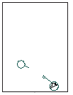
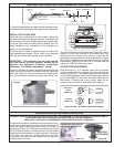
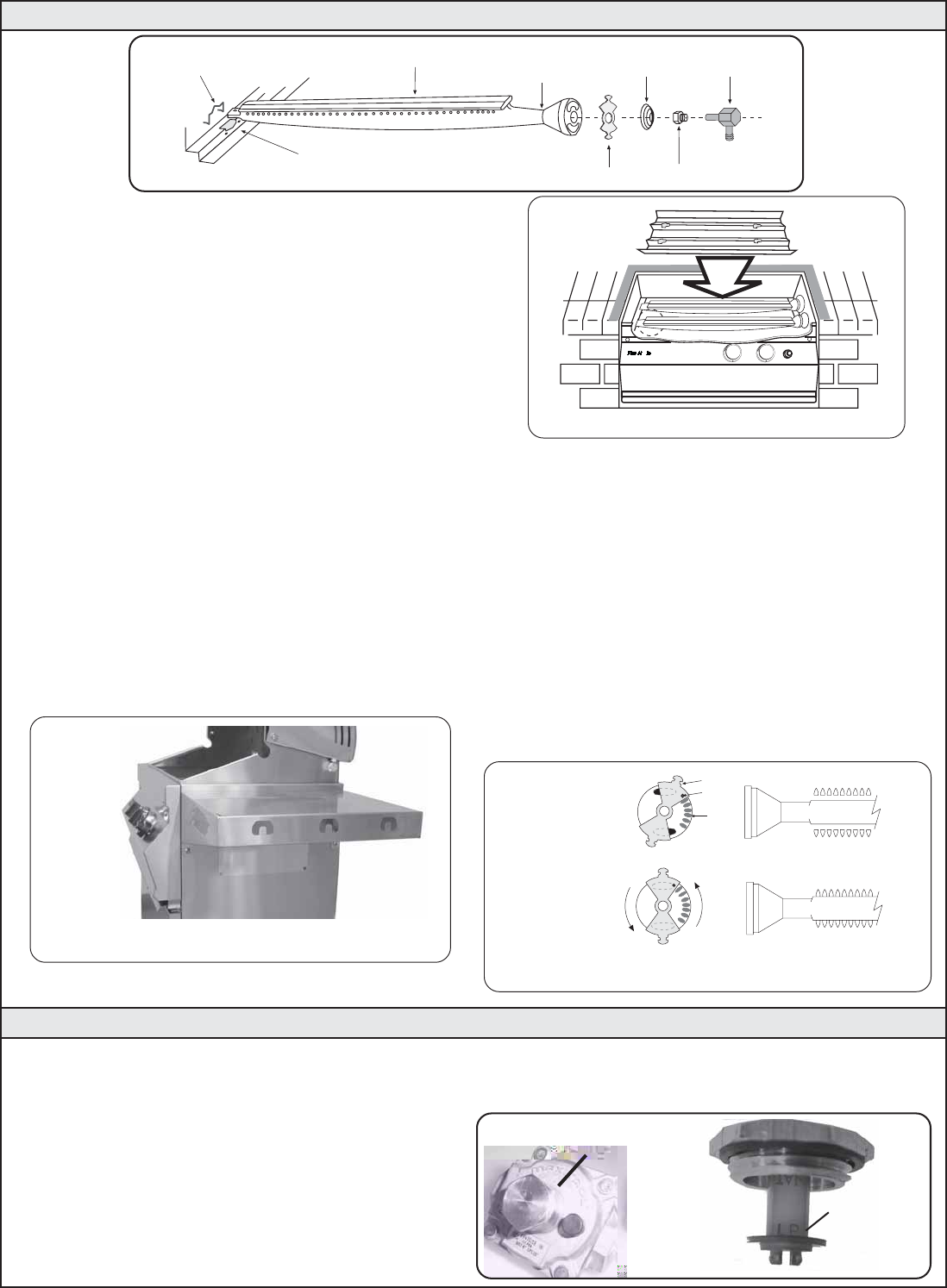
BURNER MANIFOLD
BURNER
ORIFICE
SPRING
AIR SHUTTER
BURNER NECK
HOLD DOWN
CLIP
INNER LINER
f. Carefully place the burners back so that the brass orifice
and burner manifold fittings project deeply into the burners.
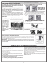
Figure 4 - Flavor Grid Diagram
INSTALL THE FLAVOR GRID
Place the flavor grids directly on the burners. Center the
grid over the burners with the open side up. This allows heat
from burners to be evenly distributed through cooking area.
The flavor grid heats and cools quickly, making your Fire
Magic Barbecue very responsive to the changes you
specify in grill temperature.
The flavor grid is made of stainless steel or coated with
high temperature porcelain. Either finish is rust resistant
and may be cleaned with standard oven cleaners.
IMPORTANT: This appliance will not light and will
not heat evenly or cook properly unless the air
shutters are adjusted following installation
(Reference "Air Shutter Adjustment", below).
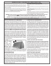
Burner air shutters are easily accessed by removing the
panel (using a hex driver), located under the right rigid
shelf (see Figure 5). The air shutters are located at the
front of the burners behind the panel (see Parts List).
Figure 3 - Burner Orifice Diagram
CHECKING AND ADJUSTING YOUR BARBECUE (CONTINUED)
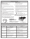
The air shutter has a small dimple (see Figure 6A), which
allows it to lock into notches in the burner face. This
prevents the air shutter from moving. Close the air
shutters by turning the tabs to a vertical position. (Figure
6B). Light your barbecue in accordance with the ‘Lighting
Instructions” (page 8) and burn for 2 minutes with the
valves on ‘HIGH’ and the oven open.
AIR SHUTTER ADJUSTMENT
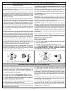
After burning for 1 to 2 minutes, open the air shutters
until the flames lift off, or appear not to be touching the
burners (Figure 6A). Then begin closing the air shutters
until the flames appear to burn while touching the burner
ports (Figure 6B). You may then see short yellow tips on
the flames. If flames are a lazy yellow, open the air
shutters until the flame is blue with yellow tipping.
The barbecue regulator, located behind the front panel (Face),
must be set for the type of gas used to fuel the barbecue. To
check the regulator setting remove the cap in the center of
the regulator (Figure 7A). Holding the cap vertical (see Figure
7B), the letters at bottom of the plastic stalk should indicate
the gas type that the reguator is currently set up for. If regulator
is not set for your gas type, remove stalk from cap, invert
and replace into center of cap. Replace cap on regulator,
screwing down until snug.
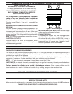
Figure 7A
Figure 7B
READ GAS
TYPE HERE
BARBECUE REGULATOR.
NOTE THE CAP ON TOP
CHECKING/CONVERTING THE BARBECUE REGULATOR.
WARNING: THIS APPLIANCE REGULATOR IS RATED FOR 1/2 PSI MAXIMUM. IF YOUR GAS SUPPLY IS GREATER THAN 1/2
PSI AN ADDITIONAL REGULATOR MUST BE INSTALLED BEFORE THE BARBECUE.
SEE PAGE 6 ("GAS SUPPLY REQUIREMENTS) FOR PROPER GAS SUPPLY PRESSURE.
PARTIALLY
OPEN
FIGURE 6A
CLOSED
FIGURE 6B
Figure 6A & 6B - Air Shutter Adjustment Diagram
FLAME ON PORTS
FLAME OFF PORTS
TAB
(TURN TABS)
DIMPLE
NOTCH
VIEW OF RIGHT RIGID SHELF
WITH ACCESS PANEL BELOW
Figure 5
OFF
HI
LIGHT
L
O
W
OFF
HI
LIGHT
L
O
W