


Special offers from our partners!

Find Replacement BBQ Parts for 20,308 Models. Repair your BBQ today.
5
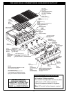
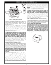
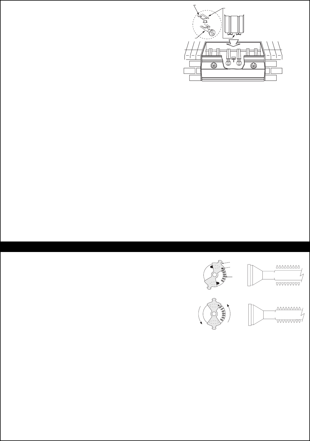
Figure 4 - Flavor Grid Diagram
3. CONNECT THE GAS SUPPLY TO BARBECUE
a. You will need an CSA approved stainless steel flex
connector to bring the gas supply from the gas line
stub to the Valve Manifold. A 1/2" x 36" or 48" flex
connector with 1/2" flare to 1/2" pipe adapter on one
end, and a 1/2" flare female fitting on the other end is
suitable for most installations. CAUTION: Use only
stainless steel flex connectors that are C.S.A.
listed.
WARNING: A rubber or plastic connector will
rupture or leak, resulting in an explosion or
serious injury if used inside the Barbecue
enclosure.
b. Make sure that your gas supply is turned off! Then
connect the 1/2" pipe adapter fitting supplied with the
stainless steel flex connector to the gas supply stub.
Use pipe joint compound that is resistant to all gasses
on the male pipe fitting and tighten securely. Do not
use pipe joint compound to connect the Flare Fittings.
c. Slide your Barbecue into place, making sure not to
pinch or kink the gas connector.
d. Bring the flex connector around the left-hand side
of the Barbecue. Use the Locator Angle Brackets on
the left lower-frame to position the flex connector.
Continue the flex connector along the left side to the
front of the unit and the Valve Manifold Inlet. Be careful
not to block the 1" Front Vent opening as this will
obstruct Drip Tray removal.
e. Connect the flex connector to the Flare Fitting on
the Manifold Inlet. Support the Manifold Inlet Fitting
with a wrench to avoid applying excessive torque to
the Manifold Assembly while tightening this connection
securely. Do not use pipe compound on Flare Fittings.
f. Make sure the Barbecue Burner valves are in the
"OFF" position. Turn the gas supply on. Then carefully
check all gas connections for leaks with a brush and
soapy water before lighting. NEVER USE A MATCH
OR OPEN FLAME TO TEST FOR LEAKS.
g. Refer to the "Air Shutter Adjustment" Instructions
below before replacing Barbecue face and knobs.
4. INSTALL THE FLAVOR GRIDS
a. Place the Flavor Grid Burner caps directly on the
Burners. Make sure the notched end of the Burner
Cap rests over the Ignitor Box (Figure 4). Center the
Grids over the Burners with the open side up. This
allows heat from the Burners to be evenly distributed
throughout the cooking area. Flavor Grids heat and
cool quickly, making your Fire Magic Barbecue very
responsive to the changes you specify in grill
temperature.
The Flavor Grids are made of stainless steel. They
are rust resistant and may be cleaned with standard
oven cleaners.
FLAVOR GRID
BURNER CAPS
NOTCH
BURNER
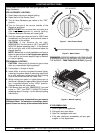
ADJUSTING YOUR BARBECUE
IMPORTANT: This appliance will not light and will
not heat evenly or cook properly unless the Air
Shutters are adjusted following installation
(Reference "Air Shutter Adjustment", below).
Burner Air Shutters are easily accessed by removing the
Front Panel (Face). The Air Shutters are located at the
front of the Burners behind the Face (see Parts List). The
Air Shutter has a small dimple (see Figure 5A), which allows
it to lock into notches in the burner face. This prevents
the air shutter from moving. Close the air shutters by turning
the tabs to a vertical position. (Figure 5B). Light your
Barbecue in accordance with lighting instructions (Page 8)
and burn for 2 minutes with the valves on high and the
oven open.
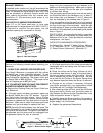
AIR SHUTTER ADJUSTMENT
After burning for 2 minutes, open the Air Shutters until
the flames lift off, or appear not to be touching the
Burners. Then begin closing the Air Shutters until the
flames appear to burn while touching the Burner Ports
(Figure 5B). You may then see short yellow tips on
the flames. If flames are a lazy yellow, open the Air
Shutters until the flame is blue with yellow tipping.
NOTE: Barbecues in some installations achieve a
better air/gas mixture and will ignite more quickly
if the valve is first turned beyond High to Medium
or Low for lighting.
ADJUSTING THE FLAME HEIGHT
The large knobs on the Face of the Barbecue control
the Valves and adjust flame height. The first position
is “High,” the second “Medium” and the final “Low.”
Flame height can also be set anywhere between the
High, Medium, and Low settings for all cooking
requirements and tastes.
Height of the flame with the
valve in low position
may be regulated by means of a small adjusting screw
in the center of the valve stem. This screw is accessible
by removing the plastic valve knob which pulls straight
off the end of the valve stem.
CLOSED
FIGURE 5B
Figure 5A & 5B - Air Shutter Adjustment Diagram
FLAME ON PORTS
FLAME OFF PORTS
TAB
(TURN TABS)
DIMPLE
NOTCH
PARTIALLY OPEN
FIGURE 5A