


Special offers from our partners!

Find Replacement BBQ Parts for 20,308 Models. Repair your BBQ today.
4
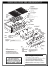
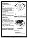
ORIFICE HOLDER/BURNER MANIFOLD
BURNER
ORIFICE
SPRING
AIR SHUTTER
BURNER NECK
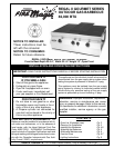
INSTALLING YOUR FIRE MAGIC REGAL II GOURMET SERIES BARBECUE
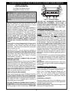
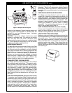
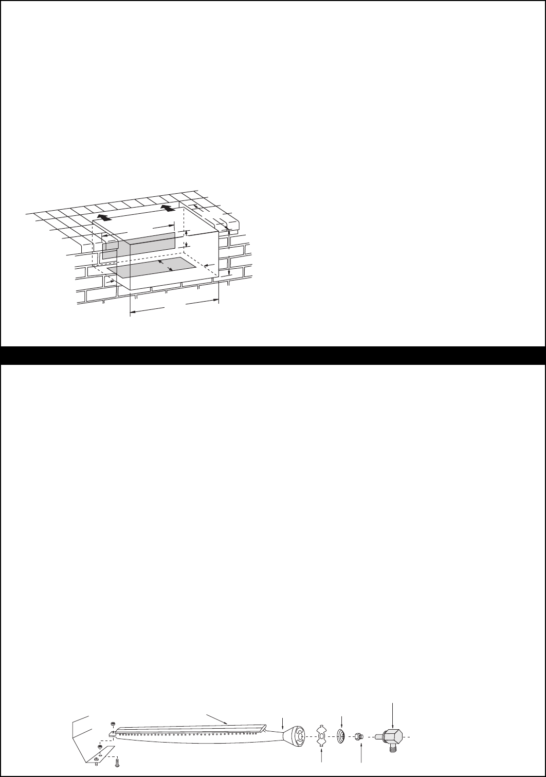
Figure 2 - Gas Stub Diagram
23 3/4"
12"
32 1/4"
28 1/4"
6"
2"
4"
2"
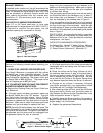
Figure 3 - Burner Orifice Diagram
EXHAUST REMOVAL
If installed under a patio roof, the grill area should be
fully covered by a non-combustible chimney and exhaust
hood. An exhaust fan with a rating of up to 1000 CFM
may be necessary to efficiently remove smoke and
other cooking by-products from the covered area.
Installation in fully-enclosed patio areas is not
recommended.
GAS SUPPLY PLUMBING REQUIREMENTS
Rigid 1/2" or 3/4" black steel pipe, or local code
approved pipe for temperatures up to 800°F (427°C),
is required to conduct the gas supply into the
enclosure opening for connection to the unit.
Perform the following checks before installing your
Barbecue:
1. CHECK FUEL ORIFICES FOR PROPER SIZE
Your Regal II Barbecue is equipped with fuel orifices
for Natural gas, unless otherwise indicated. To use
with Propane gas, you must install smaller orifices to
avoid hazardous overheating. The proper orifice size
for Natural Gas is #52 (drill size). The proper orifice
size for Propane gas is #57 (drill size).
2. IF YOU ARE NOT SURE YOU HAVE THE CORRECT
BARBECUE BURNER ORIFICE SIZE:
a. Remove the Cooking Grids and Flavor Grids from
your Barbecue.
b. If the gas supply has been connected, make sure
the Burner Valves are in the “Off” position. Then pull
the Valve knobs from their stems. Use a Phillips
screwdriver to turn the Face Fastener Screws counter
clockwise to release the Face and remove it from the
Barbecue. Make sure to retain the screws and finish
washers until you are ready to reattach the Face.
NOTE: Carefully lift the face away from the frame. The
Spark Generator for the ignition system is attached to
the inside of the face panel. The Ignitor Knob need not
be detached, but the wires must be unplugged from
the generator before the face is removed.
c. Lift off and remove one of the three galvanized steel
Heatshields which are resting over the necks of each
pair of Burners.
d. Check the orifice size by lifting a Burner up off of
the stainless steel screw, or peg, at the back side of
the unit and pulling it away from the orifice. The drill
size is stamped on the face of each orifice. Be sure
not to lose the Air Shutter or Air Shutter Spring which
may become detached when the Burner is removed.
e. Change all six orifices if necessary, following
instructions provided with your replacement orifices
(furnished with all Fire Magic Gas Barbecues).
f. After checking orifice drill size, install the Air Shutter
Spring and the Air Shutter over the orifice holder fit-
ting, between the Burner and the Pipe Manifold, in the
order and position shown in Figure 3.
g. Carefully place the Burners back on the screws or
pegs so that the brass orifice and orifice holder fittings
project deeply into the Burners.
h. Replace the galvanized Heatshields.
Apply only joint compounds that are resistant to all
gasses on all male pipe fittings. Make sure to tighten
every joint securely. Do not use pipe joint compound
to connect flare fittings.
The gas supply pipe should enter from the rear wall of
the enclosure behind the Barbecue unit, at least 2"
from either side, and between 2" and 8" above the
floor as illustrated by the shaded area in Figure 2.
If it is not possible to stub the gas line in from the back
of the enclosure, the connection may be made through
the floor at the rear of the enclosure. Install the gas
line stub at least 2" away from the side and back walls,
but within 6" of the back wall as illustrated by the shaded
area in Figure 2.
SAFETY NOTE: An external valve (with a removable
key) in the gas line is necessary for safety when your
Barbecue is not in use. It also provides for convenient
maintenance and repair.
GAS SUPPLY AND MANIFOLD PRESSURES:
For Natural Gas - Normal 7" Water Column, Minimum
3 1/2", Maximum 10-1/2". For Propane gas - Normal
11" Water Column, Minimum 8", Maximum 13".