


Special offers from our partners!

Find Replacement BBQ Parts for 20,308 Models. Repair your BBQ today.
6
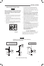
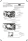
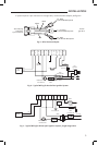
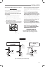
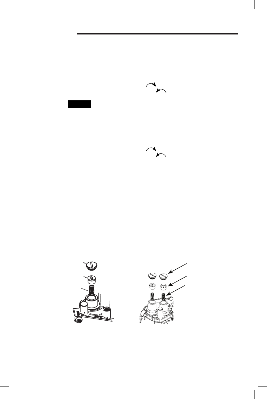
Regulator Cover Screw
Regulator
Cover Screw
Plastic
Adjust Screw
Regulator
Spring
Plastic Adjust Screw
Regulator Spring
Two-Stage Valve
Single Stage Valve
ADJUSTMENT
Fig. 8
PRESSURE REGULATOR
ADJUSTMENT
These controls are shipped from the factory set
for Natural Gas with the regulator set as specied
on the control label. Consult the appliance rating
plate to ensure burner manifold pressure is as
specied. If another outlet pressure is required,
follow these steps. For LP gas conversion, use LP
conversion kit.
NOTE
NATURAL GAS
Single Stage Models – Outlet pressure will be
factory-adjusted in the 2.5" to 5" range. The valve
cannot be adjusted outside this range.
Two-Stage Models: Low outlet pressure will be
factory- adjusted in the 1 to 4" W.C. range and
high outlet pressure will also be factory-adjusted
in the 2 to 5" W.C. range.
The valve cannot be adjusted outside this range
and the high outlet pressure setting must always
be set at least 1" above the low outlet pressure
setting.
OUTLET PRESSURE ADJUSTMENT
1. Turn o all electrical power to the system.
2. Back outlet pressure test screw out one turn,
counterclockwise, not more than one turn.
(see g. 8)
3. Attach a hose and manometer to the outlet
pressure boss of the valve.
4. Turn on system power. Set thermostat to call
for heat (low stage for two-stage systems).
Main burner should light. Proceed to step 7 for
single stage systems.
5. (2-stage only) Remove regulator cover screw
from the low outlet pressure regulator adjust
tower (g. 8) and turn screw clockwise
( ) to increase pressure, or counterclock-
wise ( ) to decrease pressure. Always
adjust regulator according to original equip-
ment manufacturer's specications listed on
the appliance rating plate. Replace regulator
cover screw.
6. (2-stage only) Set thermostat to call for high
stage.
7. Remove regulator cover screw from the single
stage or high outlet pressure regulator adjust
tower (g. 8) and turn screw clockwise
( ) to increase pressure, or counterclock-
wise ( ) to decrease pressure. Always
adjust regulator according to original equip-
ment manufacturer's specications listed on
the appliance rating plate. Replace regulator
cover screw.
8. Turn o all electrical power to the system.
9. Remove manometer hose and turn outlet
pressure test screw in to seal pressure port
(clockwise, 7 in-lb minimum).
10. Turn on electrical power to the system.
11. Turn on system power and energize valve.
12. Using a leak detection solution or soap suds,
check for leaks at pressure boss screw. Bubbles
forming indicate a leak. SHUT OFF GAS AND
FIX ALL LEAKS IMMEDIATELY.