


Special offers from our partners!

Find Replacement BBQ Parts for 20,308 Models. Repair your BBQ today.
4
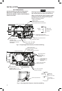
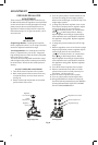
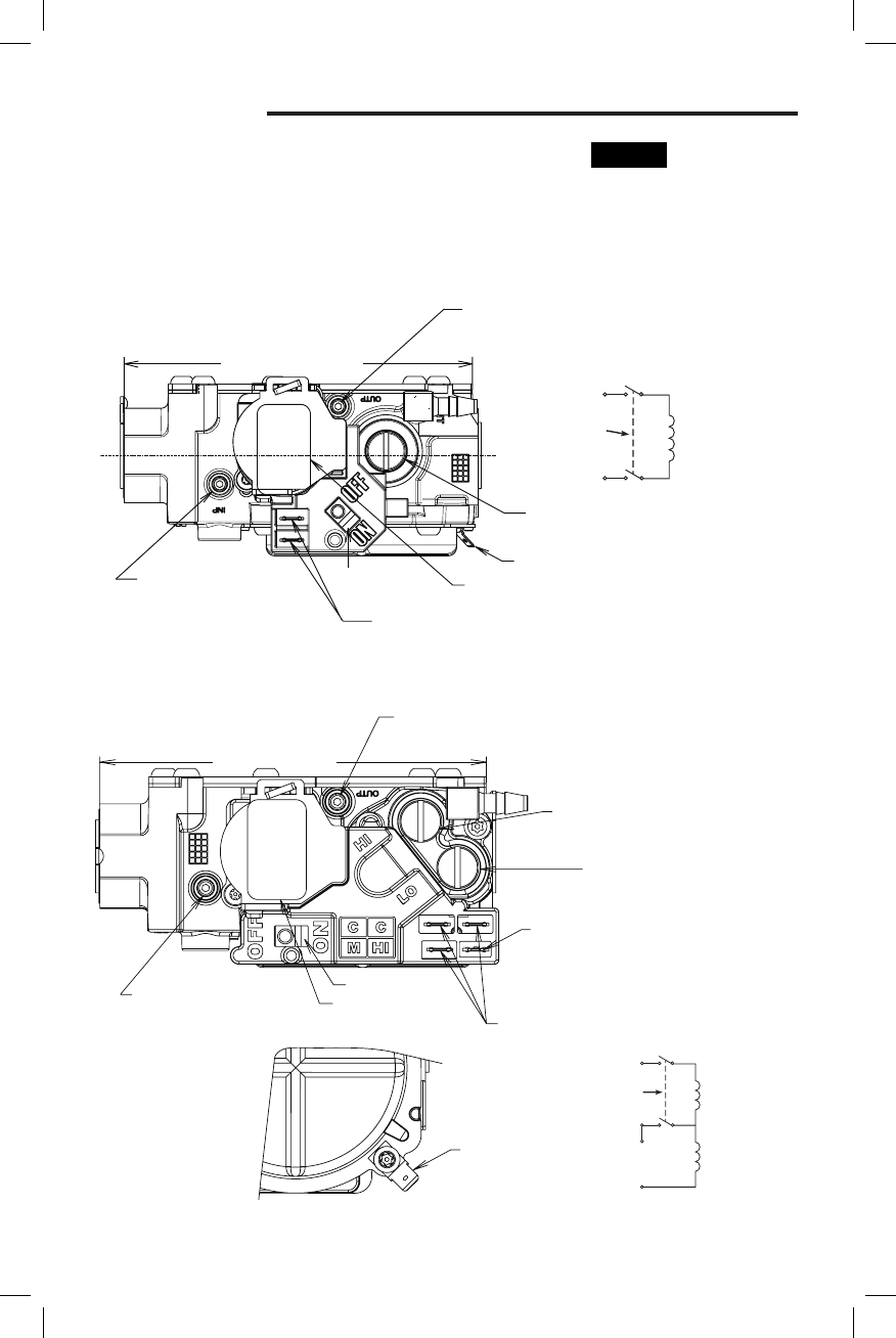
Outlet Pressure Post
Set Screw: 3/32” Hex Head
(.339 Dia. + DFT.)
Accepts 5/16” Hose Connection
Low Fire Regulator
Cover Screw
(Reg. Adj. Beneath
the Screw)
3/16” x .032” Thick Male
Spade Terminal (1)
1/4” x .032” Thick Male
Spade Terminals (3)
3/16” Ground Terminal
Control I.D. Label
Inlet Pressure Post
Set Screw: 3/32” Hex Head
(.339 Dia. + DFT.)
Accepts 5/16” Hose ConnecƟon
4.693” Inlet to Outlet
On/Off Switch
High Fire Regulator
Cover Screw
(Reg. Adj. Beneath
the Screw)
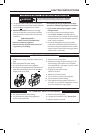
Outlet Pressure Post
.339 Dia. +DFT.
(Set Screw: 3/32” Hex Head)
Accept 5/16” ID Hose Connection
Regulator Cover Screw
(Reg. Adj. Beneath This Screw)
3/16” Ground Terminal
Control I.D. Label
1/4” x .032” THK. Male
Spade Terminals (2)
Inlet Pressure Post
.339 Dia. +DFT.
(Set Screw: 3/32” Hex Head)
Accept 5/16” I.D. Hose
ConnecƟon
4.693” Inlet to Outlet
On/Off
Switch
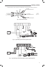
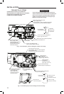
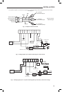
Fig. 4 – Two-Stage Valve Features, Terminals and Wiring
On/Off
Switch
Hi
M
Main and
Redundant
Valves (Low Fire)
2nd Stage
Valve (High Fire)
C
C
INSTALLATION
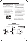
Fig. 3 – Single Stage Valve Features, Terminals and Wiring
On/Off
Switch
Main and
Redundant
Valves
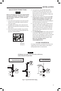
SYSTEM WIRING
REFER TO AND FOLLOW THE APPLIANCE
MANUFACTURER'S WIRING DIAGRAM.
REFER TO FIGURES 3 AND 4 FOR TERMINAL
IDENTIFICATION.
NOTE
All wiring should be installed according to local
and national electrical codes and ordinances.
Always check that the electrical power supply
used agrees with the voltage and frequency
shown on the gas control.