


Special offers from our partners!

Find Replacement BBQ Parts for 20,308 Models. Repair your BBQ today.
www.desatech.com
108862-01E 21
FIREPLACE INSTALLATION
Continued
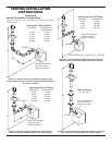
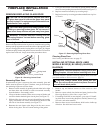
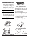
5. Place log #5 (top log) onto right pin of front log (#2) and the
smooth surface of crossover log (#4) as shown in Figure 44.
Make sure it is seated properly.
6. Place log #6 (left log) onto left pin of front log (#2) and the
smooth surface of rear log (#3) as shown in Figure 45. Make
sure it is seated properly.
7. For 42" series only, place log #7 onto right pin of top log (#5)
as shown in Figure 45. Make sure it is seated properly
8. Place lava rock along sides and front of rebox bottom in areas
that are visible only. It is not necessary to use all of the lava
rock provided.
problems.
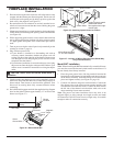
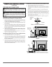
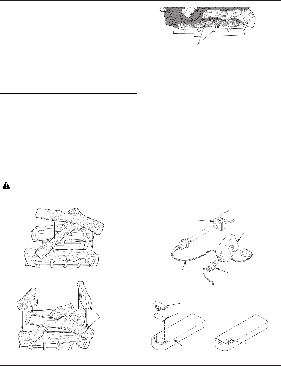
9. Pull ember material apart into pieces no larger than a dime. Place
these pieces loosely and sparingly directly onto the exposed sec-
tion of the front burner and along the space between the burner
and grate prongs (see Figure 46). This will create the glowing
ember appearance as the ame touches the ember material. Do
not block air slots by using too much ember material in one area.
It is not necessary to use all of the ember material provided.
10. Close glass door, lock door latches, replace screen, and close
louvers (see Removing/Replacing Glass Door, steps 5 through
7, page 19).
WARNING: The glass door must be securely in place
Ember Material
Figure 46 - Placing Ember Material on Burner
Figure 44 - Installing Log No. 5
5
6
7
Figure 45 - Installing Log No. 6 (36" and 42" Series) and
Log No. 7 (42" Series Only)
42" Series Only
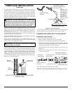
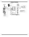
The installation of a wall switch allows you to activate the gas
control valve and turn the replace on and off. The wall switch is
to be connected to the incoming 120 volt regular household wir-
ing that supplies the electricity to the replace. Refer to wiring
diagram below.
Note: If using optional wireless hand-held remote control, the wall
switch must be in the ON position to be operational. The remote
control then becomes the switching mechanism for replace op-
eration.
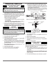
1. Open lower louver panel of rebox.
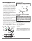
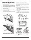
2. The WRC model receiver does not require a battery. The
receiver can be installed by rst plugging the short extension
cord into the replace receptacle. Then plug the receiver unit
into the extension cord. Finally plug the ignition module plug
into the receiver unit (see Figure 47).
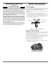
3. Activate the remote handset battery by removing the insulating
tab on the back of the handset (see Figure 48). The battery is
included pre-installed.
4. Once the battery is activated the unit is ready to use.
5. Close lower louver panel.
Figure 47 - Installing the WRC Remote Receiver
Fireplace
Receptacle
Remote Control
Receiver
Extension Cord
Ignition
Module Plug
Figure 48 - Installing Battery into Back of Handset
Pull to Remove
Insulation Tab
Battery Cover
12 Volt Battery
Back of
Handset