


Special offers from our partners!

Find Replacement BBQ Parts for 20,308 Models. Repair your BBQ today.
www.desatech.com
122274-01F12
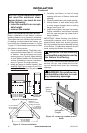
NOTICE: If your installation does
not meet the minimum clear-
ances shown, you must do one
-
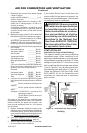
BUILT-IN FIREBOX INSTALLATION
Built-in installation of this rebox involves
installing rebox into a framed-in enclosure.
This makes the front of rebox ush with wall.
If installing a mantel above the rebox, you
must follow the clearances shown in Figure
7, page 11. Follow these instructions to install
the rebox in this manner.
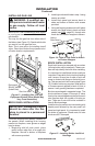
1. Frame in rough opening. The rebox fram-
ing should be constructed of 2 x 4 lumber
or heavier. Use dimensions and rough
opening layout in Figure 8. Adjust framing
so that rebox ushes with nished wall
surface. If installing in a corner, use dimen-
sions in Figure 9, for rough opening.
2. Install gas piping to rebox location. See
Installing Gas Line on page 14 and Con-
necting to Gas Supply in log set owner’s
manual.
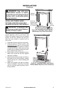
3. Carefully set firebox in front of rough
opening with back of rebox inside wall
opening.
4. Carefully insert rebox into rough opening.
5. Attach rebox to wall studs using nails
or wood screws through holes in nailing
ange (see Figure 10).
6. Install and properly test gas log heater.
Follow installation instructions included
with the vent-free gas log heater that is
being installed.
IMPORTANT: When nishing your rebox,
combustible materials such as wall board,
gypsum board, sheet rock, drywall, plywood,
etc. may be butted up next to the sides and top
of the rebox. Combustible materials should
never overlap the rebox front facing.
WARNING: Do not allow any
IMPORTANT: Noncombustible materials such
as brick, tile, etc. may overlap the front fac-
ing, but should never cover any necessary
openings.
WARNING: Do not allow non-
INSTALLATION
Continued
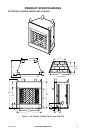
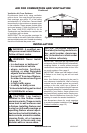
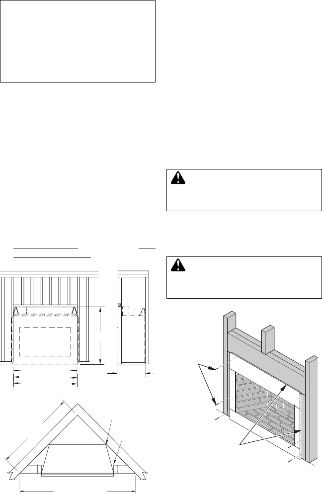
Figure 10 - Attaching Firebox to Wall
Studs
Nailing
Flanges
Nails or
Wood
Screws
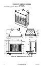
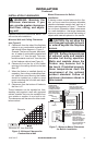
Figure 8 - Framing Dimensions
71" (50" Models)
100" (50" Models)
65" (42" Models)
92" (42" Models)
86.5" (36" Models)
61" (36" Models)
Maintain 1
1
/
2
"
Clearance at Sides
and Back of Fireplace
1
1
/
2
" Clearance
Not Required at
Nailing Flanges
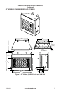
Figure 9 - Corner Installation
30.125"
59.375" (50" Models)
54.625"
51.375" (42" Models)
45.375" (36" Models)
28.250"
(36" Models)