


Special offers from our partners!

Find Replacement BBQ Parts for 20,308 Models. Repair your BBQ today.
www.desatech.com
122274-01F 11
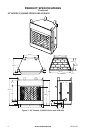
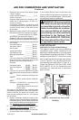
INSTALLATION CLEARANCES
WARNING: Maintain the
-
Carefully follow the instructions below. This
will ensure safe installation.
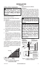
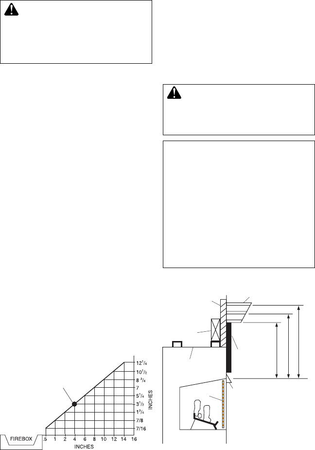
A. Clearances from the side of the replace
cabinet to any combustible material and
wall should follow diagram in Figure 6.
Example: The face of a mantel, bookshelf,
etc. is made of combustible material and
protrudes 3
1
/
2
" from the wall. This com-
bustible material must be 4" from the side
of the replace cabinet (see Figure 4).
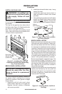
B. Clearances from the top of the rebox
opening to the ceiling should not be less
than 42".
C. When the rebox is installed directly on
carpeting, tile or other combustible mate-
rial, other than wood ooring, the rebox
should be installed on a metal or wood
panel extending the full width and depth
of the enclosure.
D. Clearances from the bottom of rebox to
the oor is 0".
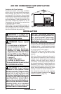
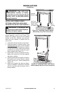
These reboxes can be installed as free-
standing units against a wall with approved
cabinet mantels that may be available from
your retailer or supplier, or as a built-in unit.
The clearances are the same for either instal-
lation method.
INSTALLATION
Continued
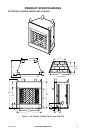
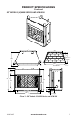
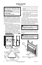
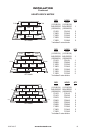
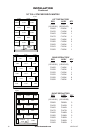
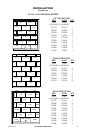
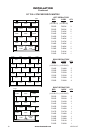
Mantel Clearances for Built-In
Installation
If placing custom mantel above built-in re-
box, you must meet the minimum allowable
clearance between mantel shelf and top of
rebox opening shown in Figure 7. These are
the minimum allowable mantel clearances
for a safe installation. Use larger clearances
wherever possible to minimize the heating of
objects and materials placed on the mantel.
CAUTION: Do not allow the
minimum clearances shown in
Figure 7 - Minimum Mantel Clearances
for Built-In Installation
Supplied
Firebox Hood
Must Be Used
at All Times
Wire-mesh
Screen
Firebox
Noncombustible
Material May
Project Off this
Surface above
the Firebox Hood
Mantel Shelf
Note: Any portion of the
mantel shelf must NOT
extend beyond this profile.
12" 16" 20"
1
1
/
2"
6
3
/
4
"
12"
Note: All vertical
measurements are
from top of fireplace
hood opening to
bottom of mantel shelf.
These minimum
clearances replace any
other recommended
clearances supplied
with your ANSI Z21.11.2
approved gas logs.
Wall board or facing
material (above
firebox) may be of
combustible material,
including decorative
mantel ornaments or
other similar projec-
tions off of the facing
material.
Framing
Material
Figure 6 - Minimum Clearance for
Combustible to Wall
*Minimum 16" from Side Wall
Example
*