


Special offers from our partners!

Find Replacement BBQ Parts for 20,308 Models. Repair your BBQ today.

www.desatech.com
116192-01B
20
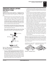
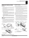
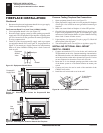
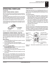
Figure 33 - Equipment Shutoff Valve
Open
Closed
Equipment
Shutoff
Valve
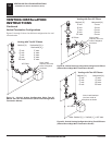
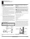
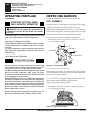
Figure 35 - Checking Gas Joints for Natural Gas Fireplace
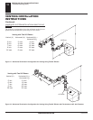
Figure 34 - Checking Gas Joints for Propane/LP Gas
Fireplace
Propane/LP
Supply Tank
Gas Valve
Equipment
Shutoff
Valve
Gas
Meter
Gas Valve
Equipment
Shutoff
Valve
FIREPLACE INSTALLATION
Continued
FIREPLACE INSTALLATION
Checking Gas Connections (Cont.)
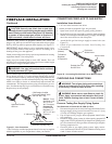
Installing Optional Wall Mount Switch - GWMS2
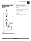
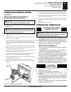
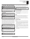
Figure 36 - Connecting Wall Swith to Control Valve
To Wall Switch
Accessory
5. Reconnect fireplace and equipment shutoff valve to gas supply.
Check reconnected fittings for leaks.
Test Pressures Equal To or Less Than 1/2 PSIG (3.5 kPa)
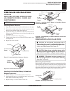
1. Close equipment shutoff valve (see Figure 33).
2. Pressurize supply piping system by either opening propane/LP
supply tank valve for propane/LP gas fireplace or opening main
gas valve located on or near gas meter for natural gas fireplace
or using compressed air.
3. Check all joints from propane/LP supply tank or gas meter
to equipment shutoff valve (see Figure 34, for propane/LP or
Figure 35, for natural gas). Apply noncorrosive leak detection
fluid to all joints. Bubbles forming show a leak. Correct all
leaks at once.
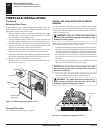
Pressure Testing Fireplace Gas Connections
1. Open equipment shutoff valve (see Figure 33).
2. Open propane/LP supply tank valve for propane/LP fireplace
or main gas valve located on or near gas meter for natural gas
fireplace.
3. Make sure control knob of fireplace is in the OFF position.
4. Check all joints from equipment shutoff valve to gas valve (see
Figure 34 for propane/LP or Figure 35 for natural gas). Apply
noncorrosive leak detection fluid to all joints. Bubbles forming
show a leak. Correct all leaks at once.
5. Light fireplace (see Operating Fireplace, page 23). Check all
other internal joints for leaks.
6. Turn off fireplace (see To Turn Off Gas to Appliance, page 24).
INSTALLING OPTIONAL WALL MOUNT
SWITCH - GWMS2
1. Connect one terminal of 25 ft. wire for the wall switch to the
TPTH terminal on the valve. Connect remaining wire terminal to
the TH terminal on the valve. Make sure that the wire terminals
are in the positions on the unit as pictured in Figure 36. If wires
are not connected as shown the switch will not work.
2. Route the 25 ft. wire through openings provided on the sides
of the burner system to a convenient location to mount your
switch.
3. Connect one bare wire end to each of the terminals of the
GWMS2 wall switch.
4. Install the wall switch and cover in the wall.