


Special offers from our partners!

Find Replacement BBQ Parts for 20,308 Models. Repair your BBQ today.
17
17
www.desatech.com
116192-01B
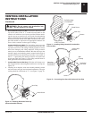
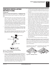
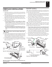
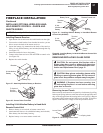
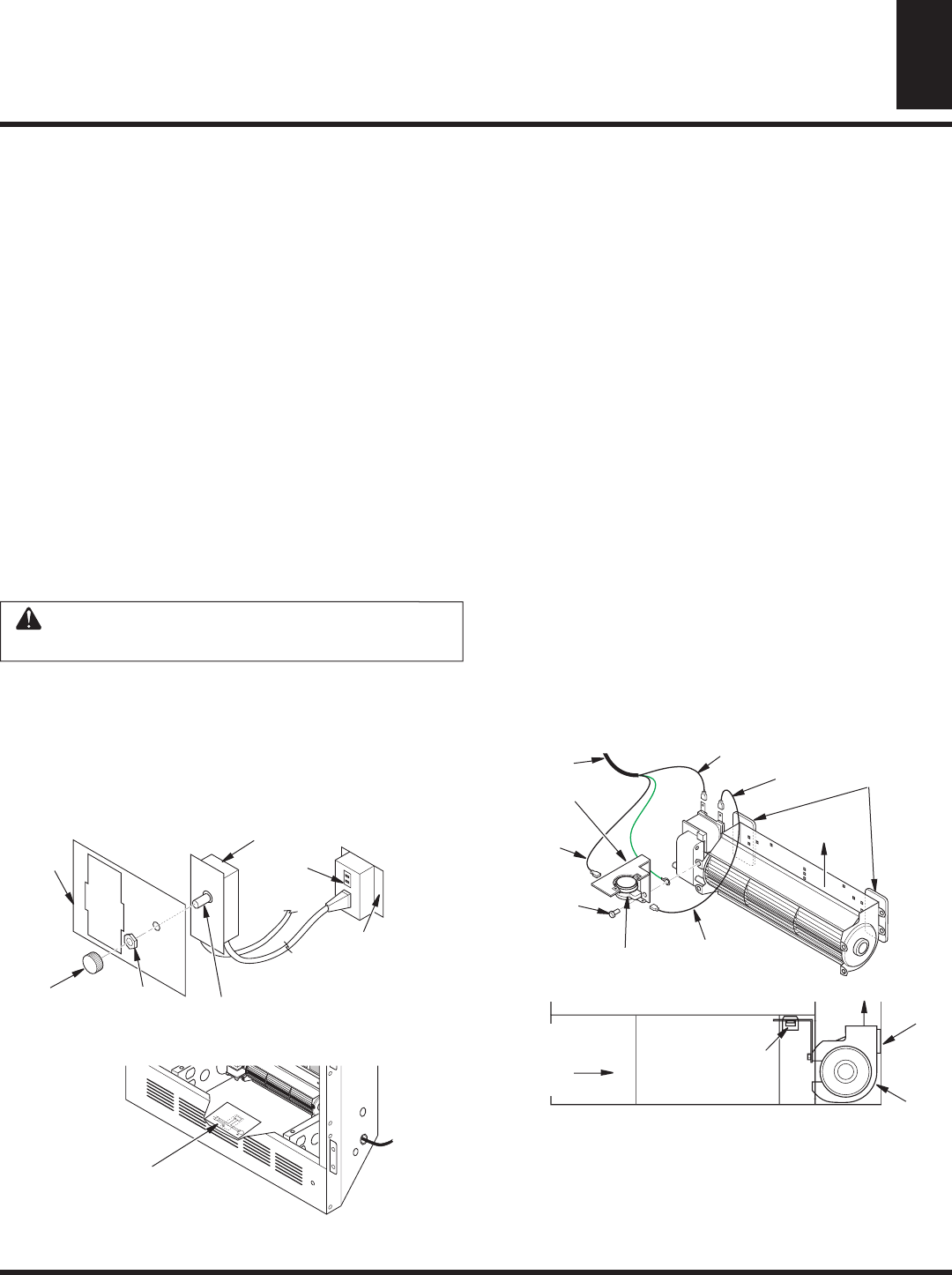
Figure 26 - Attaching Speed Control to Firebox
Speed Control
Control Shaft
Locknut
Control
Knob
Switch
Bracket
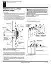
Blower
Plug-In
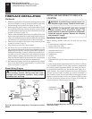
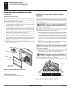
FIREPLACE INSTALLATION
Installing Optional Blower Accessories (Cont.)
Duplex Outlet
(Located
underneath firebox
floor against lower
right outside wall)
5. Mount speed control box to switch bracket by placing the plastic
control shaft forward through the round opening in the switch
bracket (see Figure 26).
6. While supporting speed control, secure control shaft with lock nut
by pushing and turning lock nut with pliers clockwise until it is
tight against front panel. Place control knob provided on shaft.
7. Turn on power to duplex outlet if previously turned off per the
warning in column 2, page 16.
8. Plug in blower power cord.
a. If your firebox is installed as a freestanding unit with an
accessory mantel, determine whether the power cord will
exit the left side or the right side of the firebox. Route power
cord through exit hole and plug the power cord into a wall
receptacle near the firebox.
b. If your firebox installation is recessed and/or pre-wired, plug
the power cord into the duplex outlet provided. Refer to your
firebox ownerʼs manual for instructions on wiring the duplex
outlet.
CAUTION: Never touch the blower wheel while
in operation.
9. Check to make sure that the power cord is completely clear of the
blower wheel and that there are no other foreign objects in blower
wheel. Turn blower on and check for operation. Turn blower off
by turning knob fully counterclockwise before continuing.
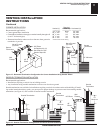
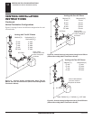
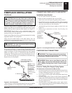
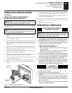
10. Peel off the backing paper and stick the supplied wiring diagram
decal on the firebox bottom approximately 12" in front of the
blower (see Figure 27).
V
ar
ia
bl
e
F
a
n
Sw
it
c
h
W
hi
t
e
W
hi
te
Bl
a
c
k
Gr
e
en
On
11
0
/
1
1
5
V
.
A
.
C
.
Bl
o
w
e
r
M
o
t
o
r
B
l
a
c
k
B
l
ac
k
Bl
a
ck
Of
f
Figure 27 - Location of Wiring Diagram Decal (Model May Vary
From Illustration)
Wiring Diagram Decal
12" in Front of Blower
FIREPLACE INSTALLATION
Continued
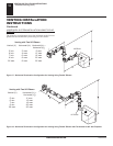
Thermodisc
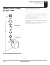
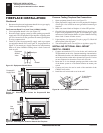
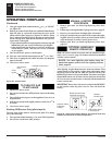
Figure 28 - Blower Model BKT
Air Flow Direction
Route BKT
Blower Through
This Area
Magnets
Blower
Location
Side View Firebox Bottom
Black
Wire
Phillips
Screw
Blue Wire
Ring Terminal
on Green Wire
White Wire
Thermal Switch
Thermal
Switch
Bracket
Power Cord
Air Flow
Direction
Magnetic
Strips
Model BKT Installation
Note: When installing the BKT thermostatically-controlled blower,
you must first secure the thermal switch bracket to the blower if it
has not already been factory installed.
1. Place the green ground wire with ring terminal between the
bottom hole on the thermal switch bracket and the top ear hole
on the blower assembly. Insert the phillips screw into all three
pieces and tighten securely (see Figure 28).
2. Connect wire harness and power cord terminals. Connect the
blue jumper wire to the blower motor terminal and the right
side terminal of the thermal switch. Connect the black wire to
the left side of the thermal switch and the white wire to the
other remaining blower motor terminal.
Note: The power cord outer insulation sleeve may have to be
stripped slightly to allow enough wire length to reach and make
all connections. DO NOT trim excessive length away. Just enable
enough to make all connections securely.
3. Place the blower against the lower rear wall of the firebox outer
wrapper with the exhaust port directed upward and the thermodisc
positioned up near the fireplace bottom. The thermodisc must
be oriented near the fireplace bottom as shown in Figure 28 in
order to sense temperature and properly operate. The blower
will be held in position against the back wall by the magnets
incorporated onto the blower housing (see Figure 28).
4. Be certain that all wire terminals are securely attached to ter-
minals on blower motor and thermal switch and that the screw
for the thermodisc bracket and green ground wire is tight.