


Special offers from our partners!

Find Replacement BBQ Parts for 20,308 Models. Repair your BBQ today.

www.desatech.com
119304-01A 9
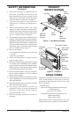
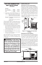
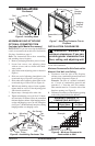
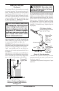
Figure 5 - Installing Hood
Screw
Hood
Rail
INSTALLATION
Continued
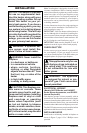
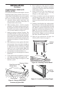
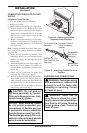
Figure 6 - Assembling Perimeter Trim
Side Trim
Slot
Mitered
Edge
Slot
Shim
Set Screws
Adjusting
Plate
Assembled
Trim
Top
Trim
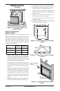
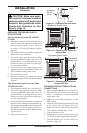
Figure 7 - Attaching Perimeter Trim to
Fireplace
Trim
Hanging
Screws
Hanging
Notches
on Trim
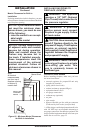
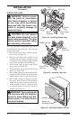
INSTALLATION CLEARANCES
WARNING: Maintain the
Carefully follow the instructions below. This will
ensure safe installation.
A. Clearances from the side of the fireplace
cabinet to any combustible material and wall
should follow diagram in Figure 8.
Example: The face of a mantel, bookshelf,
etc. is made of combustible material and
protrudes 3
1
/
2
" from the wall. This combus-
tible material must be 4" from the side of the
replace opening (see Figure 8).
B. Clearances from the top of the replace opening
to the ceiling should not be less than 42".
MINIMUM CLEARANCE TO
0" 16" 0"
*Minimum 16" from Side Wall
Figure 8 - Minimum Clearance for
Combustible to Wall
*
Example
Mitered
Edge
IMPORTANT: If you are recessing the rebox in
a wall, do not attach trim at this time. See Built-In
Fireplace Installation, page 11.
Note: The instructions below show assembling
and attaching trim to replace.
1. Remove packaging from three pieces of trim.
2. Locate four screws, two adjusting plates
with set screws, and two shims in the hard-
ware packet.
3. Align shim under adjusting plate as shown in
Figure 6.
4. Slide one end of adjusting plate/shim in slot
on mitered edge of top trim (see Figure 6).
5. Slide other end of adjusting plate/shim in slot
on mitered edge of side trim (see Figure 6).
6. While rmly holding edges of trim together,
tighten both set screws on the adjusting plate
with slotted screwdriver.
7. Repeat steps 1 through 6 for other side.
8.
Tighten trim hanging screws (#10 x 6.25 shoul-
der) into holes in cabinets. Place the assembled
trim onto replace cabinet. Align hanging notches
on trim with hanging screws on side of replace
(see Figure 7). Push trim rmly into place, sliding
hanging notches over hanging screws.