


Special offers from our partners!

Find Replacement BBQ Parts for 20,308 Models. Repair your BBQ today.
www.desatech.com
116238-01E 29
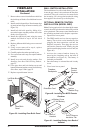
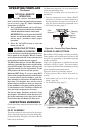
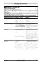
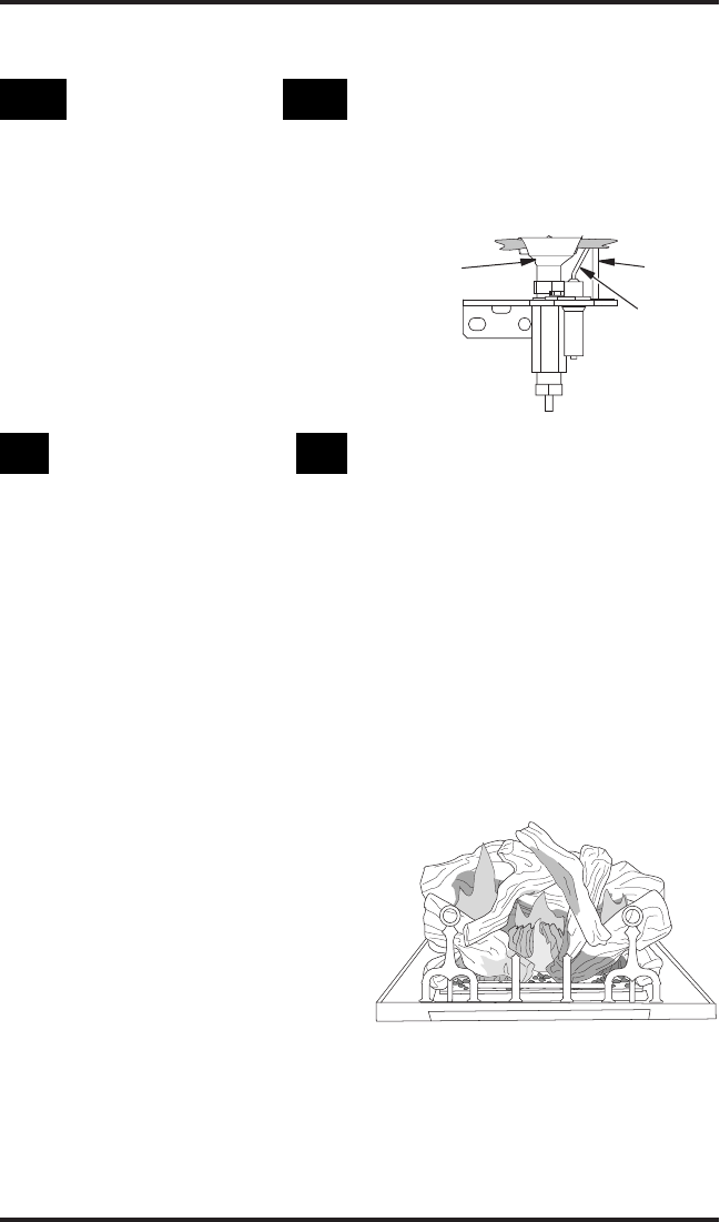
Figure 45 - Typical Flame Pattern
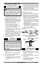
OpTIONAL REMOTE
OpERATION
Note:TheWRCreceiverandhand-heldre-
motecontrolkitmustbepurchasedseparately
(seeAccessories,page35).Followinstallation
instructionsonpage26.
1. TurnequipmentshutoffvalvetoONposi-
tion.Youcannowturntheburneronandoff
withthehand-heldremotecontrolunit.
IMPORTANT:BesuretopresstheON/OFF
buttonsonthehand-heldremotecontrol
unitforupto3secondstoassureproper
operation.
2. Press the ON/OFF buttonto turnthe
burneronandoff.
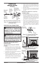
OpERATING OpTIONAL
Locatetheblowercontrolsbyopeningthelower
louverpanelonthereplace.Blowercontrols
arelocatedontheleftsideoftheswitchbracket
totherightjustinsidethelouverpanel.
TheBKmanualblowerandtheBKTthermo-
statically-controlledblowerhaveanONsetting
andanOFFsetting.Theblowerwillonlyrun
whentheswitchisintheONposition.Inthe
OFFposition,theblowerwillnotoperate.
Ifyou areusingBKT
blowerwithoptionalthermostat(wallmounted
orremotecontrol)forthereplace,yourre-
placeandblowerwillnotturnonandoffatthe
sametime.Thereplacemayrunforseveral
minutesbeforetheblowerturnson.Afterthe
heatermodulatestothepilotposition,theblow-
erwillcontinuetorun.Theblowerwillshutoff
afterthereboxtemperaturedecreases.
Theblowerhelps distribute heated airfrom
thereplace.Periodicallycheckthelouversof
thereboxandremoveanydust,dirtorother
obstructionsthatwillhindertheowofair.
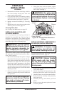
INSPECTING BURNERS
Check pilot ame pattern and burner ame pat-
terns often.
The pilot assembly is factory preset for the proper
ame. Alterations may have occurred during ship-
ping and handling. The pilot is located on the left
hand side of the burner.
OPERATING FIREPLACE
Continued
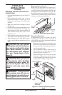
Pilot
Burner
Ignitor/
Sensor
Figure 44 - Correct Pilot Flame Pattern
Sensing
Rod
The ame must envelope 1/4" of top of the ignitor/
sensor and grounding stem.
If your pilot assembly does not meet these re-
quirements:
• Turn the adjustment screw marked PILOT
clockwise to decrease or counterclockwise to
increase the ame to proper size (see Figure 42,
page 28). Do not remove the adjustment screw.
• see Troubleshooting, page 31
Burner ames will be steady; not lifting or oating.
Flame patterns will be different from unit to unit
and will vary depending on installation type and
weather conditions.
If the vent conguration is installed incorrectly,
the ames will lift or "ghost". This can be danger-
ous. Inspect the ames after installation to ensure
proper installation and performance.
Figure 45 shows a typical ame pattern.
If burner flame pattern differs from that de-
scribed:
• turn replace off (see To Turn Off Gas to Ap-
pliance, page 28)
• see Troubleshooting, page 31