


Special offers from our partners!

Find Replacement BBQ Parts for 20,308 Models. Repair your BBQ today.
www.desatech.com
116238-01E 15
TERMINATION
Note: Vertical restrictor must be installed in all
vertical installations.
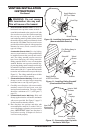
1. Determine the route your vertical venting
will take. If ceiling joists, roof rafters or other
framing will obstruct the venting system,
consider an offset (see Figure 19) to avoid cut-
ting load bearing members. Note: Pay special
attention to these installation instructions for
required clearances (air space) to combustibles
when passing through ceilings, walls, roofs,
enclosures, attic rafters, etc. Do not pack air
spaces with insulation. Also note maximum
vertical rise of the venting system and any
maximum horizontal offset limitations.
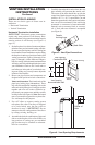
2. Set the replace in desired location. Drop a
plumb line down from the ceiling to the posi-
tion of the replace exit ue. Mark the center
point where the vent will penetrate the ceiling.
Drill a small locating hole at this point.
Drop a plumb line from the inside of the roof
to the locating hole in the ceiling. Mark the
center point where the vent will penetrate the
roof. Drill a small locating hole at this point.
1.
Cut a 10
3
/
4
" square hole in the ceiling using
the locating hole as a center point. The open-
ing should be framed to 10
3
/
4
" x 10
3
/
4
" inside
dimensions, as shown in Figure 9 on page 10
using framing lumber the same size as the
ceiling joists. If the area above the ceiling is an
insulated ceiling or an attic, nail restop from
the top side. This prevents loose insulation from
falling into the required clearance space. If the
area above the ceiling is a living space, install
restop below the framed hole. The restop
should be installed with no less than three nails
per side (see Figure 20).
2. Assemble the desired lengths of pipe and
elbows necessary to reach from the replace
ue up through the restop. Be sure all pipe
and elbow connections are fully twist-locked
(see Figure 8, page 10).
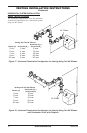
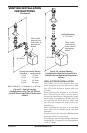
3. Cut a hole in the roof using the locating hole
as a center point. (Cover any exposed open
vent pipes before cutting hole in roof.) The
10
3
/
4
" x 10
3
/
4
" hole must be measured on
the horizontal; actual length may be larger
depending on the pitch of the roof. There
must be a 1" clearance from the vent pipe to
combustible materials. Frame the opening as
shown in Figure 9, page 10.
4. Connect a section of pipe and extend up
through the hole.
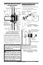
Note: If an offset is needed to avoid obstruc-
tions, you must support the vent pipe every 3
feet. Use wall straps for this purpose (see Fig-
ure 19). Whenever possible, use 45° elbows
instead of 90° elbows. The 45° elbow offers
less restriction to the ow of the ue gases
and intake air.
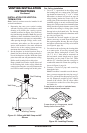
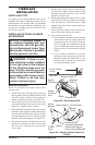
VENTING INSTALLATION
INSTRUCTIONS
Continued
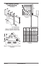
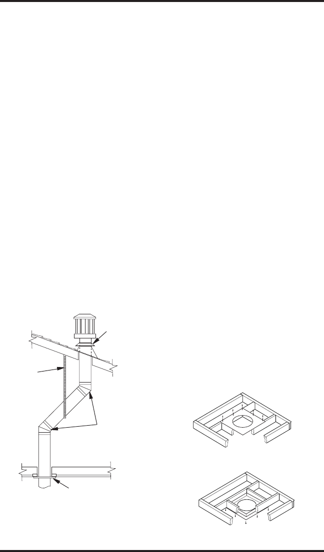
Figure 19 - Offset with Wall Strap and 45°
Elbows
45° Elbow
Wall Strap
Roof Flashing
Ceiling Firestop
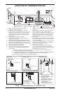
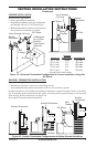
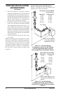
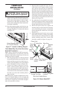
Figure 20 - Installing Firestop
If area above is a living space, install
restop below framed hole.
If area above is an attic or insulated area,
install restop above framed hole.