


Special offers from our partners!

Find Replacement BBQ Parts for 20,308 Models. Repair your BBQ today.
111924-01C
For more information, visit www.desatech.com
For more information, visit www.desatech.com
18
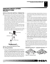
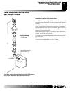
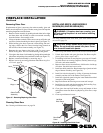
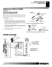
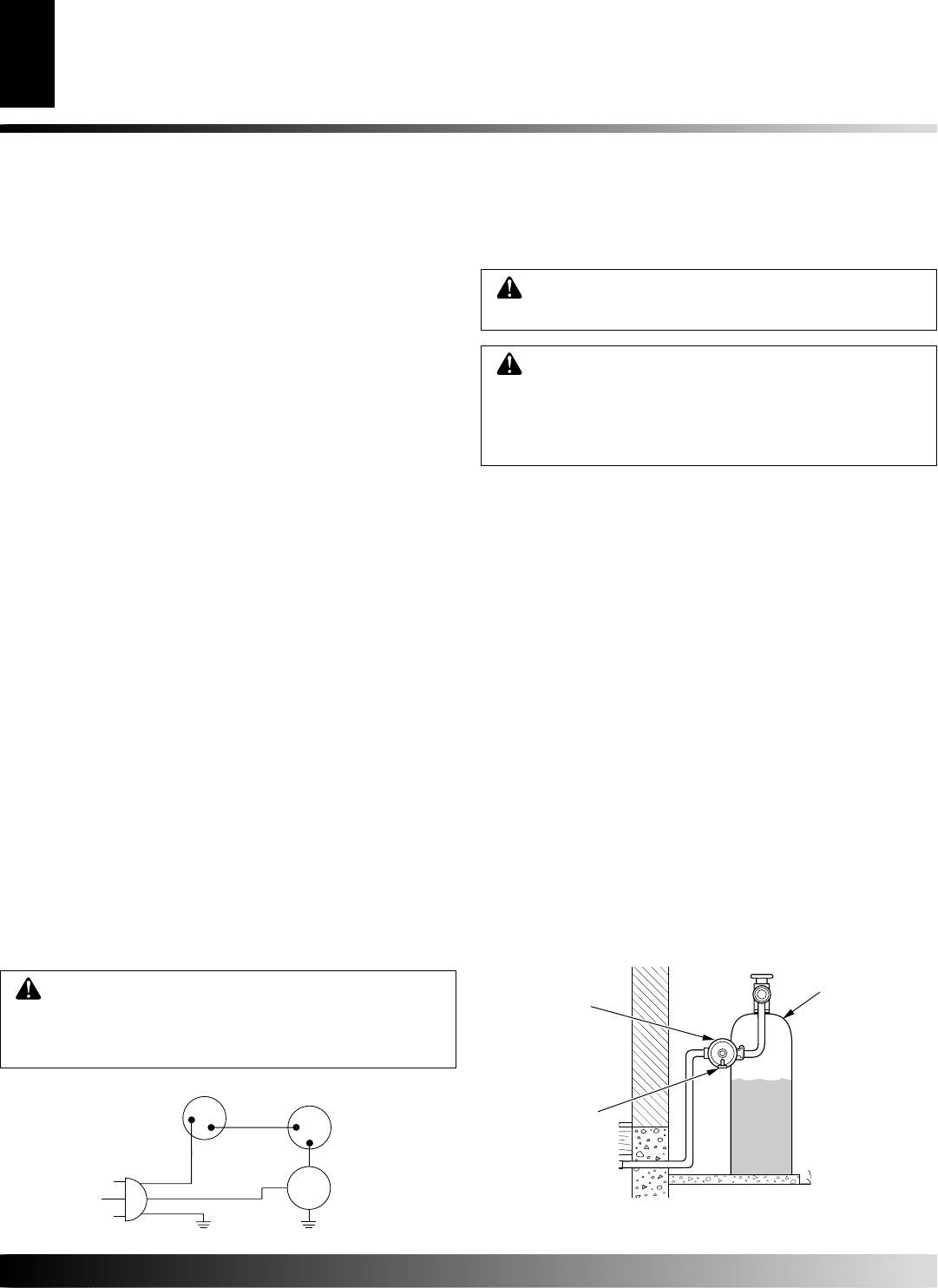
Figure 29 - Blower Wiring Diagram for Thermostat-Controlled Models
Blower Wiring Diagram
CAUTION: Label all wires prior to disconnection
when servicing controls. Wiring errors can cause
improper and dangerous operation. Verify proper
operation after servicing.
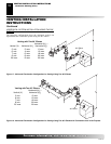
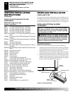
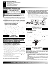
INSTALLING GAS PIPING TO FIREPLACE
LOCATION
Installation Items Needed
Before installing fireplace, make sure you have the items listed below.
• external regulator (supplied by installer)
• piping (check local codes)
• sealant (resistant to propane/LP gas)
• equipment shutoff valve *
• test gauge connection *
• sediment trap
• tee joint
• pipe wrench
• approved flexible gas line with gas connector (if allowed by lo-
cal codes)
* A CSA design-certified equipment shutoff valve with 1/8" NPT tap
is an acceptable alternative to test gauge connection. Purchase the
CSA design-certified equipment shutoff valve from your retailer.
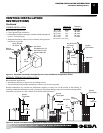
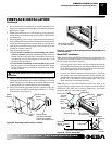
For propane/LP connection only, the installer must supply an
external regulator. The external regulator will reduce incoming gas
pressure. You must reduce incoming gas pressure to between 11 and
14 inches of water. If you do not reduce incoming gas pressure,
fireplace regulator damage could occur. Install external regulator
with the vent pointing down as shown in Figure 31, page 19.
Pointing the vent down protects it from freezing rain or sleet.
WARNING: A qualified service person must con-
nect fireplace to gas supply. Follow all local codes.
CAUTION: For propane/LP units, never connect
fireplace directly to the propane/LP supply. This
heater requires an external regulator (not supplied).
Install the external regulator between the fireplace
and propane/LP supply.
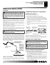
Figure 30 - External Regulator with Vent Pointing Down
(Propane/LP Only)
Propane/LP
Supply Tank
External
Regulator
Vent
Pointing
Down
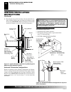
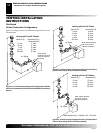
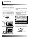
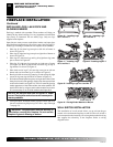
3. Place the blower against the lower rear wall of the firebox outer
wrapper with the exhaust port directed upward and the thermodisc
positioned up near the fireplace bottom. The thermodisc must be
oriented near the fireplace bottom as shown in Figure 28, page
17, in order to sense temperature and properly operate. The blower
will be held in position against the back wall by the magnets
incorporated onto the blower housing (see Figure 28, page 17).
4. Be certain that all wire terminals are securely attached to ter-
minals on blower motor and thermal switch, and that the screw
for the thermodisc bracket and green ground wire is tight.
5. Mount the speed control box against the mounting plate pro-
vided in the lower fireplace cavity by placing the plastic control
shaft forward through the round hole (see Figure 26, page 17).
6. While supporting speed control, secure control shaft with lock
nut by pushing and turning lock nut with pliers clockwise un-
til it is tight against mounting plate. Place control knob pro-
vided on shaft (see Figure 26, page 17).
7. Check to make sure that the power cord is completely clear of the
blower wheel and that there are no other foreign objects in blower
wheel. Also double check all wire leads and make sure wire rout-
ing is not pinched or in a precarious position. Correct accordingly.
8. Turn on power to duplex outlet if previously turned off per the
warning in column 2, page 16.
9. Plug in blower power cord to duplex outlet.
10. The blower will only run when the speed control knob is in the
ON position and the thermal switch senses temperature after the
fireplace begins to heat up. The blower speed can be adjusted by
rotating the control knob. To turn off, turn knob fully counter-
clockwise until it clicks off. If the blower is ON and has been
running with the fireplace operating, the blower will continue to
run for a short time after the fireplace has been turned off. As the
thermal switch cools down, the blower shuts down automatically.
11. Peel off the backing paper and stick the supplied wiring dia-
gram decal on the firebox bottom approximately 12" in front
of the blower (see Figure 27, page 17).
.
FIREPLACE INSTALLATION
Continued
FIREPLACE INSTALLATION
Installing Optional Blower Accessory (Cont.)
Installing Gas Piping to Fireplace Location
Variable
Fan Switch
Fan Switch
(N.O.)
On
Off
1
2
Black
Green
White
110/115
V.A.C.
Blower
Motor
Black
Blue