


Special offers from our partners!

Find Replacement BBQ Parts for 20,308 Models. Repair your BBQ today.
www.desatech.com
116526-01B12
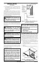
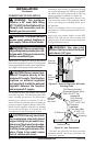
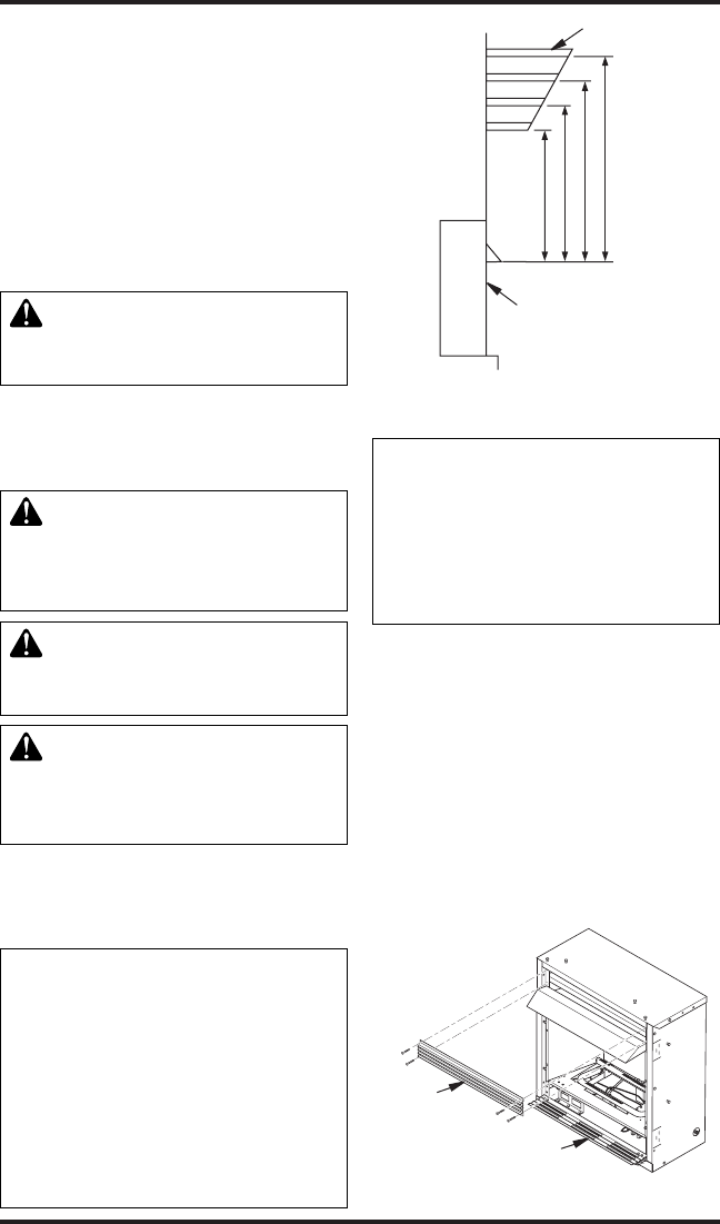
15"
18"
21"
23"
2
1
/
2
"
6"
8"
10"
Note:
A
ll vertical
measurements
are from top of
fireplace
opening to
bottom of
mantel shelf. All
measurements
are in inches.
10. If using optional trim kit, install the trim after
nal nishing and/or painting of wall. See
instructions included with trim accessory for
attaching trim.
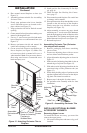
IMPORTANT: When finishing your firebox,
combustible materials such as wall board, gypsum
board, sheet rock, drywall, plywood, etc. may be
butted up next to the sides and top edge of the re-
box. Combustible materials should never overlap
the rebox front facing.
WARNING: Do not allow any
combustible materials to overlap
IMPORTANT: Noncombustible materials such as
brick, tile, etc. may overlap the front facing, but
should never cover any necessary openings like
louvered slots.
WARNING: Do not allow
noncombustible materials to
WARNING: Never modify or
cover the louvered slots on the
WARNING: Use only noncom-
bustible mortar or adhesives when
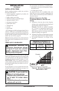
Mantel Clearances for Built-In Installation
If placing mantel above built-in replace, you must
meet minimum clearance between mantel shelf and
top of replace opening.
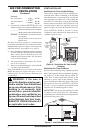
NOTICE: Surface temperatures
-
If installed properly, these tem-
peratures meet the requirement
Follow all minimum clearances
INSTALLATION
Continued
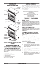
Figure 10 - Minimum Mantel Clearances
for Built-In Installation
Mantel Shelf
Side of Firebox
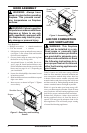
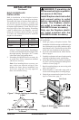
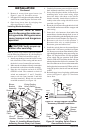
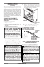
Figure 11 - Removing Top Louver and
Opening Bottom Louver
O
F
F
P
I
L
O
T
O
N
H
I
L
O
Top
Louver
Bottom Louver
NOTICE: If your installation does
not meet the minimum clear-
ances shown, you must do one
• raise the mantel to an accept-
• remove the mantel
Note: Refer to instructions provided with the mantel
for assembly instructions. Refer to the following
instructions for system installation. Refer to instruc-
tions on page 4 for hood assembly. Blower accessory
should be installed if it is being used (see Installing
Optional Blower Accessory GA3450TA, page 13).
1. Unscrew four screws that attach top louver to
replace. Remove louver from replace and
set aside (see Figure 11).
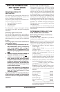
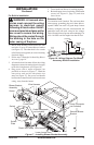
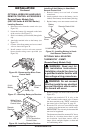
2. Place base assembly next to wall at installation
location.
3. Place replace on wood base (see Figure 12).