


Special offers from our partners!

Find Replacement BBQ Parts for 20,308 Models. Repair your BBQ today.
www.desatech.com
111906-01F18
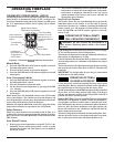
FIREPLACE INSTALLATION
Continued
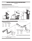
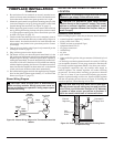
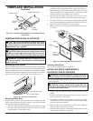
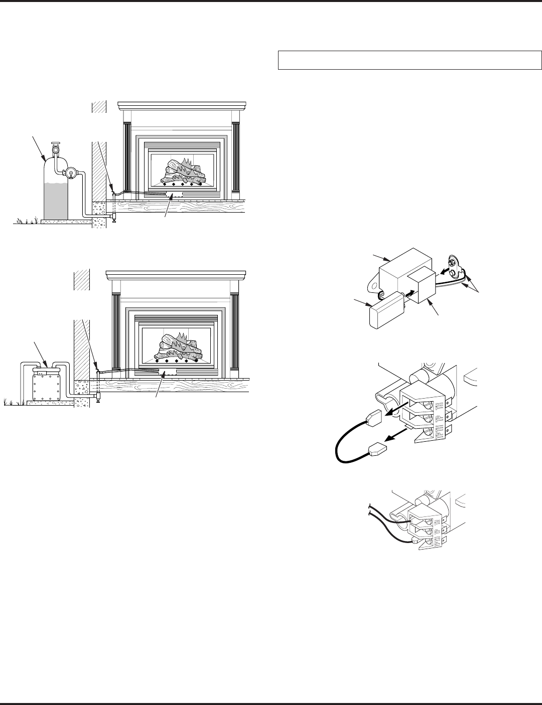
Figure 35 - Checking Gas Joints for Natural Gas Fireplace
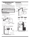
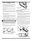
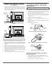
Figure 34 - Checking Gas Joints for Propane/LP Gas
Fireplace
Propane/LP
Supply Tank
Gas Valve
Equipment
Shutoff
Valve
Gas
Meter
Gas Valve
Equipment
Shutoff
Valve
3. Check all joints from propane/LP supply tank or gas meter to
equipment shutoff valve (see Figure 34 or 35). Apply noncor-
rosive leak detection uid to all joints. Bubbles forming show
a leak. Correct all leaks at once.
1. Open equipment shutoff valve (see Figure 33, page 17).
2. Open propane/LP supply tank valve for propane/LP replace
or main gas valve located on or near gas meter for natural gas
replace.
3. Make sure control knob of replace is in the OFF position.
4. Check all joints from equipment shutoff valve to gas valve (see
Figure 34 or 35). Apply noncorrosive leak detection uid to all
joints. Bubbles forming show a leak. Correct all leaks at once.
5. Light replace (see Operating Fireplace, page 21). Check all
other internal joints for leaks.
6. Turn off replace (see To Turn Off Gas to Appliance, page 22).
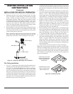
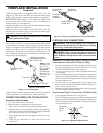
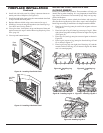
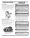
INSTALLING OPTIONAL WIRELESS HAND-
Installing Remote Receiver
1. Open bottom louver and locate the switch bracket on the left.
2. Unscrew the switch bracket. Lean bracket forward so you are
able to access the back of the remote receiver.
3. Locate the battery clip mounted on the back of the receiver.
Slide a 9-volt alkaline battery (not included) through the clip
(see Figure 36).
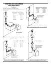
4. Attach the terminal wires to the battery.
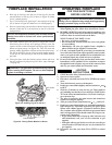
5. Remove wires from TH to TPTH on control valve (see
Figure 37).
6. Connect wires from receiver to TH and TPTH to control valve
(see Figure 38).
7. Replace the switch bracket.
Figure 37 - Connecting Wall Switch to Control Cover
To Wall
Thermostat
1. Remove battery cover on back of remote control unit.
2. Attach terminal wires to a 9-volt alkaline battery (not included).
Place battery into the battery housing.
3. Replace battery cover onto remote control unit.
Figure 36 - Attaching Alkaline Battery to Receiver
Figure 38 - Control Valve Terminals
To Optional
Remote
Accessory
9-Volt
Alkaline
Battery
Receiver
Terminal
Wires
Battery Clip