


Special offers from our partners!

Find Replacement BBQ Parts for 20,308 Models. Repair your BBQ today.
11
104887
OWNER’S MANUAL
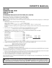
A.G.A. Design-
Certified Manual
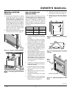
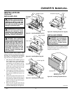
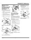
Shutoff Valve With
1/8" NPT Tap*
3" Minimum
From Gas
Meter (5"
W.C. to
10.5" W.C.
Pressure)
Approved Flexible
Gas Line
Cap Pipe Tee
Nipple Joint
Sediment Trap
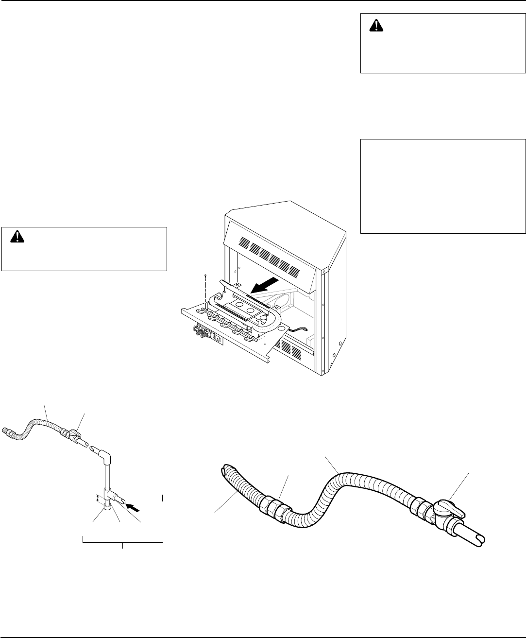
Figure 16 - Gas Connection
* Purchase the optional A.G.A. design-cer-
tified manual shutoff valve from your dealer.
See Accessories, pages 24 and 25
CAUTION: Use pipe joint seal-
ant that is resistant to liquid pe-
troleum (LP) gas.
Install sediment trap in supply line as shown
in Figure 16. Locate sediment trap where it
is within reach for cleaning. Locate sedi-
ment trap where trapped matter is not likely
to freeze. A sediment trap traps moisture
and contaminants. This keeps them from
going into fireplace gas controls. If sedi-
ment trap is not installed or is installed
wrong, fireplace may not run properly.
INSTALLATION
Continued
Installation must include a manual shutoff
valve, union, and plugged 1/8" NPT tap.
Locate NPT tap within reach for test gauge
hook up. NPT tap must be upstream from
fireplace (see Figure 16).
Check your building codes for any special
requirements for locating manual shutoff
valve to fireplaces.
Apply pipe joint sealant lightly to male
threads. This will prevent excess sealant
from going into pipe. Excess sealant in pipe
could result in clogged fireplace valves.
Installation Items Needed
• 5/16" hex socket wrench or nut-driver
• Phillips screwdriver
• sealant (resistant to propane/LP gas, not
provided)
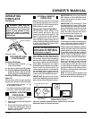
1. Remove fireplace screen. Remove two
screws that hold fireplace screen in
place for shipping. These screws are
located near top of screen. Discard
screws. Lift fireplace screen up and pull
out to remove.
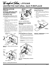
2. Remove screws that attach log base
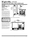
assembly to fireplace (see Figure 17).
Carefully lift up log base assembly and
remove from fireplace (see Figure 17).
CONNECTING FIREPLACE
TO GAS SUPPLY
CAUTION: Do not pick up log
base assembly by burners. This
could damage burners. Only
handle base by grates.
Continued
3. Route flexible gas line (provided by
installer) from manual shutoff valve to
fireplace. Route flexible gas supply line
through one of the access holes.
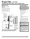
Figure 17 - Removing Log Base Assembly
From Fireplace
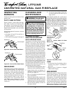
Figure 18 - Attaching Flexible Gas Lines Together
4. Attach a 45° flare union gas connector
to flexible gas line from gas supply (see
Figure 18). Connect flare union to flex-
ible gas line attached to gas regulator
of fireplace (see Figure 18).
5. Check all gas connections for leaks. See
Checking Gas Connections, page 12.
6. Replace log base assembly back into
fireplace. Feed flexible gas line into fire-
place base area while replacing log base
assembly. Make sure the entire flexible
gas line is in fireplace base area. Reat-
tach log base assembly to fireplace with
screws removed in step 2.
Flexible Gas Line
from Fireplace Gas
Regulator Provided
With Fireplace
To Fireplace
Gas Regulator
Flare Union
Flexible Gas Line from
Manual Shutoff Valve
Provided By Installer
Manual Shutoff Valve
➞
NOTICE: Most building codes do
not permit concealed gas con-
nections. A flexible gas line is
provided to allow accessibility
from the fireplace (see Figure 18).
The flexible gas supply line con-
nection to the manual shutoff
valve should be accessible.
➞
To Gas Meter
O
F
F
P
I
L
O
T
O
N
H
I
L
O