


Special offers from our partners!

Find Replacement BBQ Parts for 20,308 Models. Repair your BBQ today.
9
901261
OWNER’S MANUAL
INSTALLATION
Continued
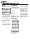
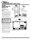
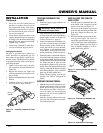
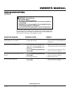
Figure 7 - Checking Gas Joints
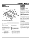
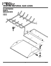
HEARTH KIT ASSEMBLY
AND INSTALLATION
Kit Assembly
1. Unscrew burner inlet fitting from
burner manifold.
2. Place burner manifold in pan with
threaded opening facing open knock-
out plug (see Figure 8). Make sure the
burner ports face downward.
3. Using thread sealant (resistant to the
action of propane/LP gas) on larger
end of fitting, screw the burner inlet
fitting through hole and into burner
manifold. Tighten using a wrench. If
using propane/LP gas, see Propane/LP
Gas Conversion, pages 10 and 11.
4. If using optional GA9000 kit, go to Op-
tional GA9000 On/Off Safety Valve/Pi-
lot Kit section for installation instruc-
tions. If using optional GA9100 kit,
follow instructions included with kit for
installation and operation.
Continued
Test Pressures Equal To or Less Than
1/2 PSIG (3.5 kPa)
1. Close equipment shutoff valve (see Fig-
ure 7).
2. Pressurize supply piping system by either
using compressed air or opening main gas
valve located on or near gas meter.
3. Check all joints from gas meter to equip-
ment shutoff valve (see Figure 7). Apply
mixture of liquid soap and water to gas
joints. Bubbles forming show a leak.
4. Correct all leaks at once.
Gas Meter
Equipment Shutoff
Valve
Installation and Gas Connection
1. Place the burner pan assembly in the
center of the fireplace floor. Make sure
the inlet end of the pan faces the gas
supply.
2. Thread the gas supply fitting to the
fireplace gas supply pipe. Use thread
sealant.
3. Install adapter fitting onto the burner
inlet fitting using thread sealant on
male threads of burner inlet fitting
(see Figure 9). Adjust to most conve-
nient position.
4. Install the gas connector tube to the gas
supply fitting. Carefully shape tube to
attach to adapter fitting. Be careful not
to cause kinks in tube.
5. Using the 1/4" x #8 provided, install
the cover over the inlet fitting.
OPTIONAL GA9000 ON/OFF
SAFETY VALVE/PILOT KIT
ASSEMBLY
For additional convenience and safety, or
for propane/LP conversion, an optional ON/
OFF safety valve/pilot kit is available. See
Accessories, page 19.
WARNING: You must use a
ON/OFF safety valve/pilot kit for
propane/LP conversion.
Note:
The control cover provided with the
GA9000 should be discarded and replaced
with the one provided with the log set.
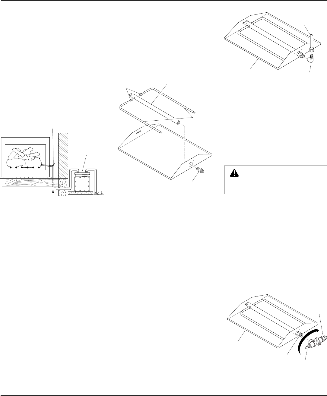
Natural Gas Installation
1. Thread the gas control valve onto the
burner inlet fitting (see Figure 10). Use
thread sealant on the male threads of
the burner inlet fitting. Hold the burner
inlet fitting with a wrench to prevent
overtightening the connection to the
burner. Make sure the control rod is
facing the front (see Figure 10).
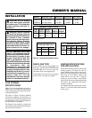
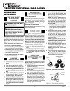
Figure 9 - Connecting Gas to Appliance
Adapter
Fitting
Gas
Connector
Tube
Burner Inlet
Fitting
Gas
Control
Valve
Burner Pan
Assembly
Figure 10 - Installing Gas Control Valve
Control Rod
Burner Pan
Assembly
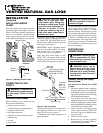
5. Using thread sealant on the male
threads, install the burner connection
fittings into the 1/8" NPT holes on each
side of the burner manifold.
6. Press the right and left side burners onto
the burner connection fittings. The
burner porting should face downward
(see Figure 8).
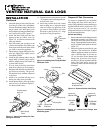
Figure 8 - Installing Burner
Burner Inlet
Fitting
Burner Manifold
Burner
Connection
Fittings
Side
Burners