


Special offers from our partners!

Find Replacement BBQ Parts for 20,308 Models. Repair your BBQ today.

10
901261
VENTED NATURAL GAS LOGS
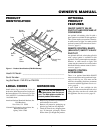
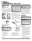
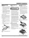
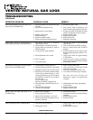
2. Attach the pilot gas line to the pilot out-
let of the gas control valve and tighten.
Connect the thermocouple to the rear of
the gas control valve. See Figure 11. Do
not overtighten. If using propane/LP gas,
see Changing Pilot Orifice, page 11.
3. Install the inlet fitting into the inlet
opening of the gas control valve (see
Figure 12). Use thread sealant on the
male pipe threads.
4. Place the burner pan assembly in the
center of the fireplace floor. Make sure
front of pan faces the room from which
you wish to control the appliance.
5. Thread the gas supply fitting to the fire-
place gas supply pipe. Adjust to most
convenient position.
6.
Install the gas connector tube to the gas
supply fitting. Carefully shape tube to
attach to adapter fitting. Be careful not
to cause kinks in tube.
7. Test for leaks following instructions
under Testing Burner for Leaks, page 11.
8.
Retighten and adjust the location of the
gas control as necessary. The gas con-
trol should be level, with the control rod
to the front.
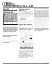
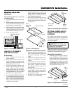
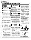
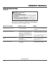
9. Install cover, provided with log set, to
burner pan using screws provided.
10. Install thermocouple, pilot, and ignitor
onto valve cover as shown in Figure 13.
Use the provided screws.
INSTALLATION
Continued
Figure 11 - Gas Control Valve with Ther-
mocouple and Pilot
Figure 12 - Installing Inlet Fitting and Gas
Connector Tube
Piezo Ignitor
Control Rod
Extension
Screw
Valve Cover
Control
Knob
Figure 13 - Installing Cover, Control Knob,
and Piezo Ignitor
Propane/LP Gas Conversion
To convert to propane/LP gas, the burner
inlet fitting and pilot orifice must be re-
placed. The propane/LP burner inlet fitting is
supplied with the orifice installed for a 24"
log set. If you have an 18" set, you must
change this orifice also. See Figure 1, page 3
for product identification.
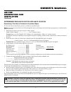
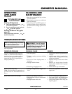
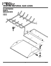
Burner Inlet Fitting
1. Remove the burner inlet fitting from the
burner pan assembly (see Figure 14).
DO NOT remove the orifice from this
fitting. The propane/LP burner inlet fit-
ting is included in the hardware kit (see
Figure 15).
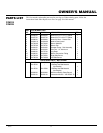
2. Be sure to use the correct orifice for your
appliance. The hardware kit included
with this appliance contains two orifices
with a cone-like shape. If you have an
18" set, the orifice for the burner inlet
fitting is red. If you have a 24" log set,
the orifice is already installed inside the
fitting. The black orifice will not be
used in any multi-side unit and may be
discarded.
Thermocouple
and Line
Pilot and Line
Gas Control
Valve
Figure 15 - Burner Inlet Fittings with
Injectors
NATURAL
GAS
FITTING
PROPANE/
LP GAS
FITTING
Injector for
Natural Gas
Injector for
Propane/LP
Gas
Gas Control
Valve
Gas Inlet
Fitting
Gas
Connector
Tube
Figure 14 - Remove Burner Inlet Fitting
Burner Inlet Fitting
for Natural Gas
Thermocouple
Ignitor
Pilot
Inlet
Opening
11. Push the control rod extension onto the
“D” shaped control rod through the cen-
ter hole in the cover.
12.
Install the position decal and control
knob making sure to align the marks
with the correct stop positions of the
gas control. Pilot position will allow
the knob to push in about 1/2". Align
the decals in the pilot position.