


Special offers from our partners!

Find Replacement BBQ Parts for 20,308 Models. Repair your BBQ today.
8
103573
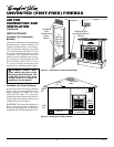
UNVENTED (VENT-FREE) FIREBOX
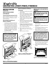
Duplex
Outlet
Screw
Support
bracket
Side
Opening
Support Bracket
Opening
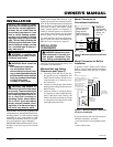
Blower Power
Cord
Blower
INSTALLATION
Continued
INSTALLING BLOWER
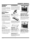
ACCESSORY
You may install blower accessory GA3750
with conventional installation (below) or with
built-in installation (page 10). To install
blower accessory, see instruction sheet in-
cluded with the kit.
Conventional Installation of
Blower Accessory
1. Install blower assembly per instruction
sheet included in blower accessory kit.
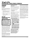
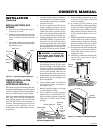
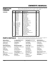
2. Before replacing bottom of firebox,
route blower power cord through hole
in support bracket in bottom of firebox
and through hole in side of firebox to
grounded, three-prong 120 volt electri-
cal outlet (see Figure 8). Plug electri-
cal cord into outlet.
3. Replace bottom of firebox.
NOTICE: A certified electrician
must connect electrical wiring to
duplex outlet for built-in installa-
tion. Follow all local codes. In
absence of local codes, follow
the
National Electrical Code, ANS/
NFPA 70 (Latest Edition)
.
INSTALLING LOG HEATER IN
FIREBOX
CAUTION: Do not pick up log
base assembly by burners. This
could damage burners. Only
handle base by grates.
CAUTION: Do not remove the
metal data plates attached to the
heater base assembly. The data
plates contain important warranty
information.
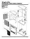
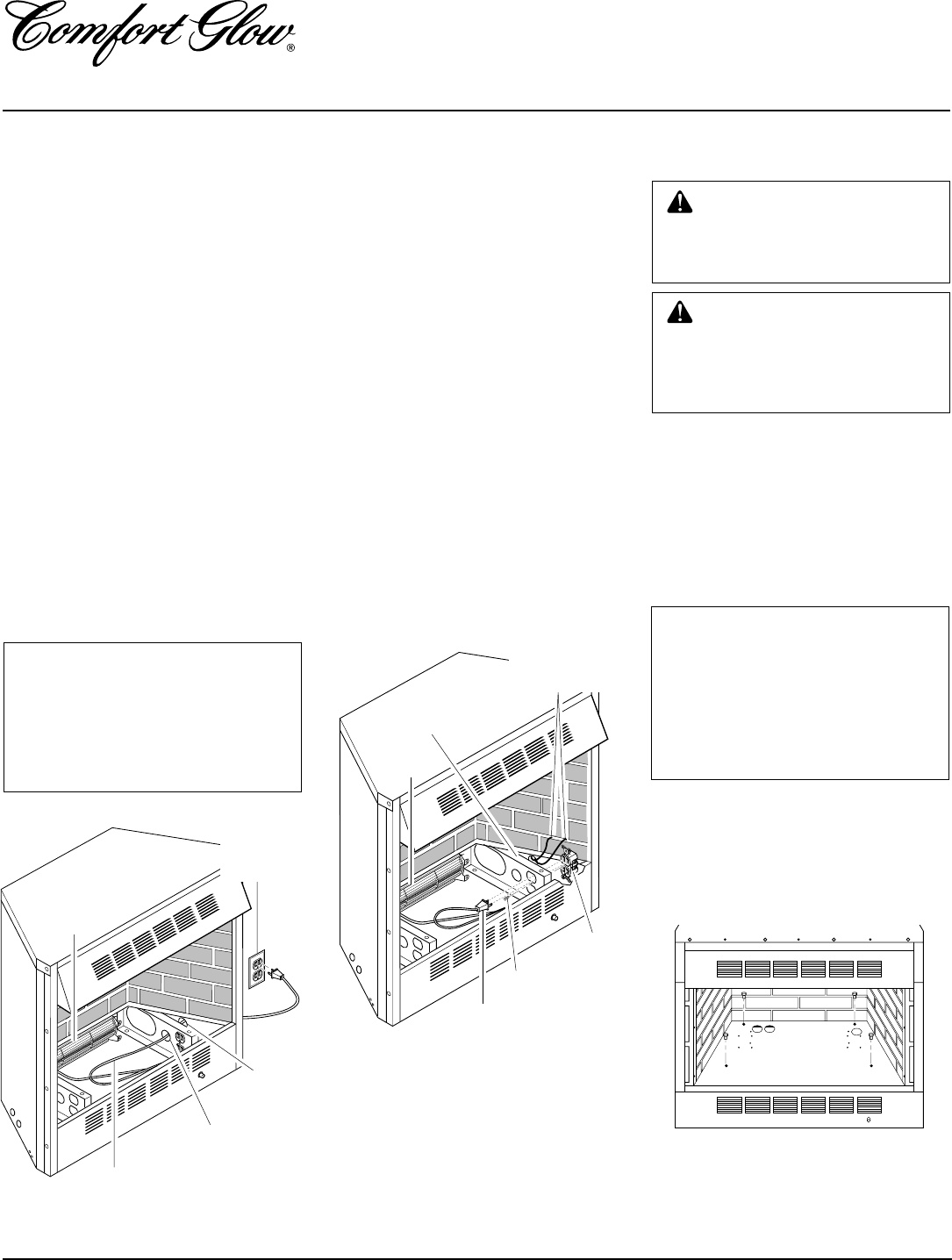
1. Remove four screws holding firebox
bottom in place.
2. Lift and remove firebox bottom (see
Figure 10).
3. If installing GA3750 blower accessory,
see Installing Blower Accessory.
4. Route flexible gas line from manual
shutoff valve into firebox through side.
NOTICE: Most building codes do
not permit concealed gas con-
nections. A flexible gas line is
recommended to allow accessi-
bility from the firebox. The flex-
ible gas supply line connection
to the manual shutoff valve
should be accessible.
5. Attach gas log heater base to firebox
bottom with four screws included with
base (see Installing Heater Base As-
sembly in log set owner’s manual).
6. Replace firebox bottom and secure with
screws.
Figure 10 - Removing Firebox Bottom
Built-In Installation of Blower
Accessory
1. Install blower assembly per instruction
sheet included.
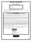
2. Before replacing bottom of firebox,
remove screw holding duplex outlet to
the support bracket in the bottom of
firebox. Remove duplex outlet.
3. Clamp electrical cable into firebox
through smallest hole using strain re-
lief provided.
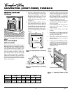
4. Route wires from electrical box through
hole in side of heater and hole in sup-
port bracket (see Figure 9).
5. Connect wires from the electrical box
to duplex outlet. Match wire colors to
those indicated on duplex outlet. Be
sure to connect ground wire.
6. Replace duplex outlet with screw.
7. Plug blower power cord into duplex
outlet.
8. Replace bottom of firebox.
Figure 8 - Routing Blower Accessory
Power Cord for Conventional Installation
Electrical
Outlet
Figure 9 - Routing Blower Accessory
Power Cord for Built-In Installation
Blower
Blower Power
Cord
Cables From
Electrical
Source