


Special offers from our partners!

Find Replacement BBQ Parts for 20,308 Models. Repair your BBQ today.
9
104277
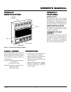
OWNER’S MANUAL
Continued
Note:
A qualified installer should make
all electrical connections.
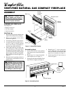
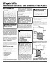
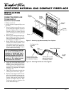
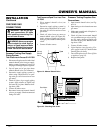
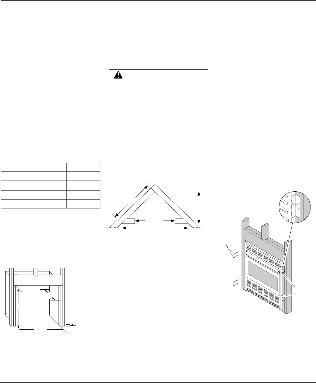
Figure 10 - Attaching Fireplace to Wall
Studs
36
5
/
8
"
25
7
/
8
"
51
3
/
4
"
26
7
/
8
"
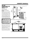
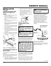
Figure 9 - Rough Opening for Installing in
Corner
2. If installing GA3400(T) blower acces-
sory, do so at this time. Follow instruc-
tions included with blower accessory.
Note:
If not installing blower acces-
sory, you may wish to run electrical
wiring to your fireplace for future
blower installation (see Accessories,
page 22). Use only approved three-wire
electrical wiring.
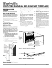
1. Frame in rough opening. Use dimen-
sions shown in Figure 8 for the rough
opening.
If installing in a corner, use dimensions
shown in Figure 9 for the rough open-
ing. The height is 26
7
/8" which is the
same as the wall opening above.
26
7
/
8
"
26
7
/
8
"
3/4" Off
The Floor
Minimum
10
1
/
2
"
Figure 8 - Rough Opening for Installing in
Wall
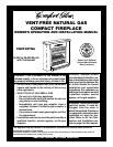
BUILT-IN FIREPLACE
INSTALLATION
Built-in installation of this fireplace involves
installing fireplace into a framed-in enclo-
sure. This makes the front of fireplace flush
with wall. An optional brass trim kit acces-
sory is available (see Accessories, page 22).
Brass trim will extend past sides of fireplace
approximately 1/2 inch. This will cover the
rough edges of the wall opening. If install-
ing a built-in mantel above the fireplace, but
you must follow the clearances shown in
Figure 11, page 10. Follow the instructions
below to install the fireplace in this manner.
Note:
Your Comfort Glow fireplace is de-
signed to be used in zero clearance installa-
tions. Wall or framing material can be placed
directly against any exterior surface on the
rear, sides, or top of your fireplace.
Actual Framing
Height 26" 26
7
/8"
Front Width 26
3
/4" 26
7
/8"
Depth 9
1
/2" 10
1
/2"
Bottom 3/4" 3/4"
INSTALLATION
Continued
Nails or
Wood
Screws
Nailing
Flanges
3. Install gas piping to fireplace location.
This installation includes an approved
flexible gas line (if allowed by local
codes) after the manual shutoff valve.
The flexible gas line must be the last
item installed on the gas piping.
4. If you have not assembled firebox, fol-
low instructions on page 4.
5. Carefully set fireplace in front of rough
opening with back of fireplace inside
wall opening.
6. Attach flexible gas line to fireplace gas
regulator. See Connecting Fireplace to
Gas Supply, page 12.
7. Bend four nailing flanges on outer cas-
ing with pliers (see Figure 10).
8. Attach fireplace to wall studs using
nails or wood screws through holes in
nailing flange.
9. Check all gas connections for leaks. See
Checking Gas Connections, page 13.
10. If using optional brass trim kit, install
the trim after final finishing and/or
painting of wall. See instructions in-
cluded with brass trim accessory for at-
taching brass trim.
WARNING: If pre-wiring, do
not connect wiring to any electri-
cal source at this time.
Install fireplace electrical outlet
and connect wiring to outlet be-
fore connecting to electrical
source. The fireplace electrical
outlet is included with the
GA3450(T) blower accessory.
Only use the fireplace electrical
outlet supplied with the
GA3450(T) blower accessory.