


Special offers from our partners!

Find Replacement BBQ Parts for 20,308 Models. Repair your BBQ today.
11
104277
OWNER’S MANUAL
CONNECTING TO GAS
SUPPLY
WARNING: A qualified ser-
vice person must connect fire-
place to gas supply. Follow all
local codes.
IMPORTANT:
Check gas line pressure
before connecting fireplace to gas line. Gas
line pressure must be no greater than 14
inches of water. If gas line pressure is higher,
fireplace regulator damage could occur.
Installation must include a manual shutoff
valve, union, and plugged 1/8" NPT tap.
Locate NPT tap within reach for test gauge
hook up. NPT tap must be upstream from
fireplace (see Figure 16).
Apply pipe joint sealant lightly to male
threads. This will prevent excess sealant
from going into pipe. Excess sealant in pipe
could result in clogged fireplace valves.
Install sediment trap in supply line as
shown in Figure 16. Locate sediment
trap where it is within reach for
cleaning. Locate sediment trap where
trapped matter is not likely to freeze.
A sediment trap traps moisture and
contaminants. This keeps them from
going into fireplace controls. If
sediment trap is not installed or is
installed wrong, fireplace may not run
properly.
WARNING: Never connect
fireplace to private (non-utility)
gas wells. This gas is commonly
known as wellhead gas.
CAUTION: Use only new,
black iron or steel pipe. Inter-
nally-tinned copper tubing may
be used in certain areas. Check
your local codes. Use pipe of 1/2"
or greater diameter to allow
proper gas volume to fireplace. If
pipe is too small, undue loss of
pressure will occur.
CAUTION: Use pipe joint seal-
ant that is resistant to liquid pe-
troleum (LP) gas.
* Purchase the optional A.G.A. design-cer-
tified manual shutoff valve from your dealer.
See Accessories, page 22.
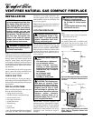
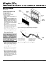
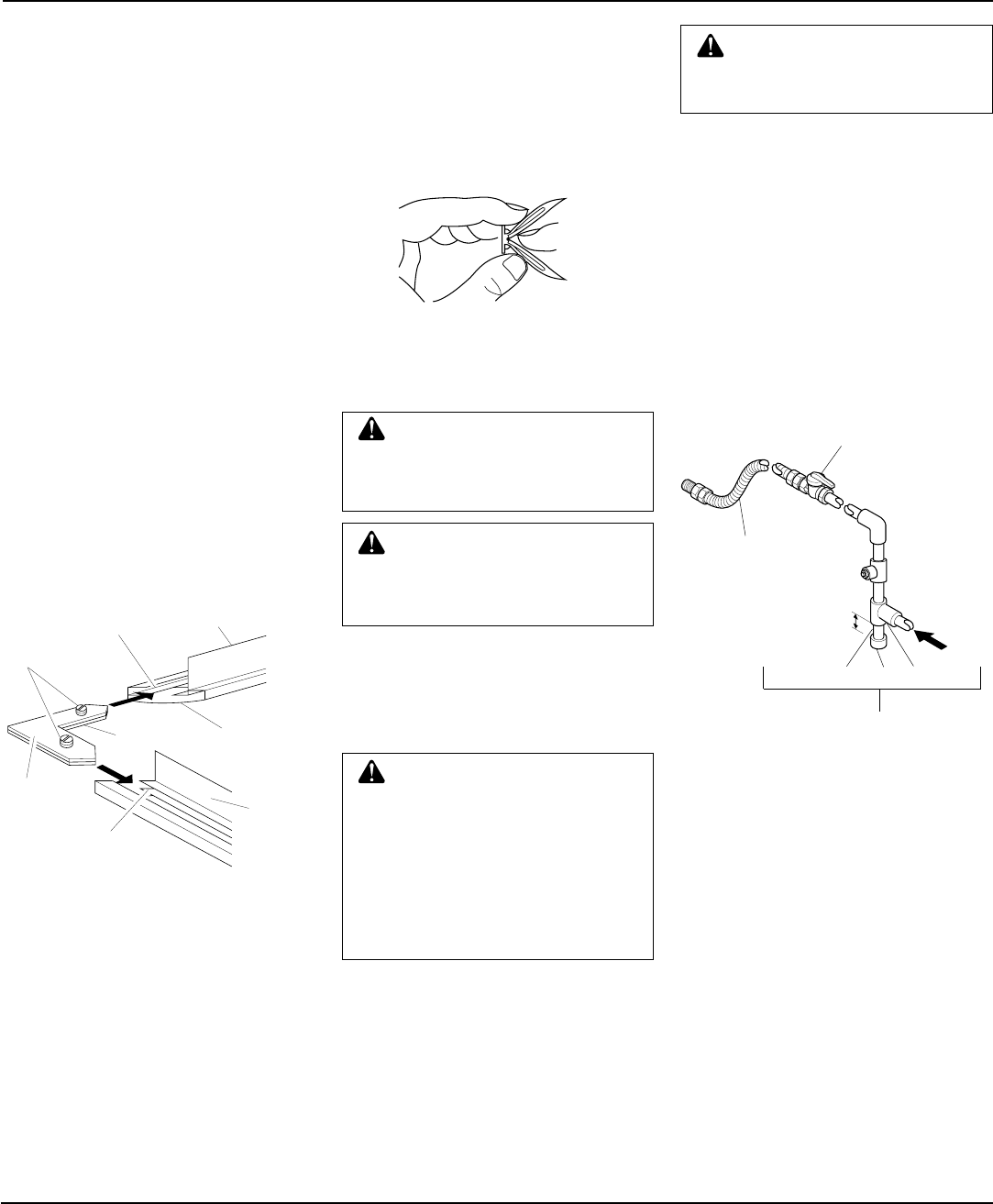
Figure 16 - Gas Connection
ATTACHING WOOD BASE TO
SOLID FLOOR
For attaching base to solid floors (concrete
or masonry)
Note:
Floor anchors and mounting screws
are in hardware package. The hardware pack-
age is provided with fireplace.
1. Drill holes at marked locations using
5/16" drill bit. For solid floors (concrete
or masonry), drill at least 1" deep.
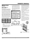
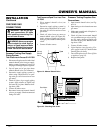
Figure 15 - Folding Anchor
ASSEMBLING BRASS TRIM
(Brass trim shipped with
mantel)
1. Remove packaging from three remain-
ing pieces of brass trim.
2. Locate two adjusting plates with set
screws, and two shims in the hardware
packet.
3. Align shim under adjusting plate as
shown in Figure 14.
4. Slide one end of adjusting plate/shim
in slot on mitered edge of top brass trim
(see Figure 14).
5. Slide other end of adjusting plate/shim
in slot on mitered edge of side brass
trim (see Figure 14).
6. While firmly holding edges of brass
trim together, tighten both set screws
on the adjusting plate with slotted
screwdriver.
7.
Repeat steps 1 through 6 for other corner.
8. Set brass a7ssembly aside for later
installation.
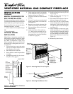
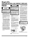
Figure 14 - Assembling Brass Trim
INSTALLATION
Continued
Top Brass Trim
Side
Brass
Trim
Mitered
Edge
Shim
Set
Screws
Adjusting
Plate
Slot
Slot
A.G.A. Design-Certified
Manual Shutoff Valve
With 1/8" NPT Tap*
3" Minimum
From Gas
Meter
(5" W.C. to
10.5" W.C.
Pressure)
Approved
Flexible Gas Line
Pipe Nipple Cap Tee Joint
Sediment Trap
2. Fold floor anchor as shown in Figure 15.
3. Insert floor anchor (wings first) into
hole. Tap anchor flush to floor.
4. Insert mounting screws through base
and into floor anchors.
5. Tighten screws until base is firmly fas-
tened to floor.
Continued