


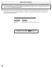
Special offers from our partners!

Find Replacement BBQ Parts for 20,308 Models. Repair your BBQ today.
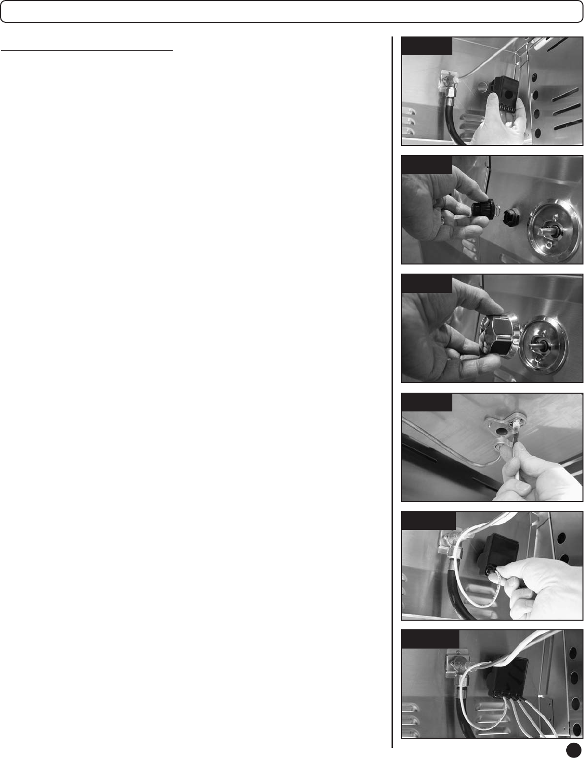
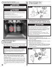
Fig. 25
Fig. 26b
Fig. 23
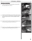
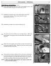
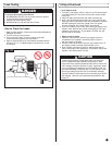
11.
Assemble the plastic hex nut and igniter button back onto
the electrode module. These items should be hand
tightened only (Fig. 23).
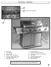
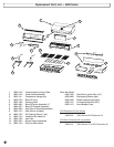
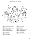
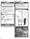
Grill Assembly — 8200 Series
Fig. 24
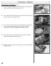
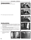
13.
The igniter wire for the side burner is shipped loose. Attach the
large spade to the igniter terminal underneath the side burner
(Fig. 25).
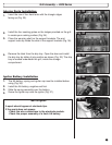
15.
Three wires are factory installed to the main burner electrodes.
Locate the loose ends of these three wires (they exit the right
side panel through a grommet) and attach them in any order to
the tabs in the back of the electrode module (Fig. 26b).
NOTE: It does not matter which ignition wire goes to which tab
on the electrode module.
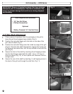
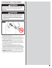
Side Burner Installation
(continued)
Fig. 22
10.
From underneath the side shelf, push the threaded portion of the
electrode module through the round hole (Fig. 22).
13
Fig. 26a
12.
Assemble the side burner control knob (Fig. 24).
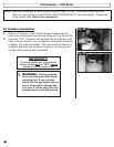
14.
Attach the small spade to one of the four open terminals on the
electrode module (Fig. 26a). Notice that the wire may be neatly
wrapped around the fuel line.