


Special offers from our partners!

Find Replacement BBQ Parts for 20,308 Models. Repair your BBQ today.
1-9
Cisco CGS 2520 Hardware Installation Guide
OL-31444-01
Chapter 1 Product Overview
LEDs
• SD Flash Memory Card LED, page 1-12
• Power Supply-Side LEDs, page 1-14
Switch Panel LEDs
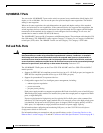
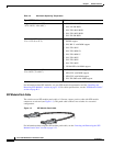
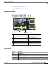
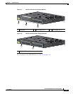
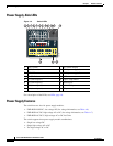
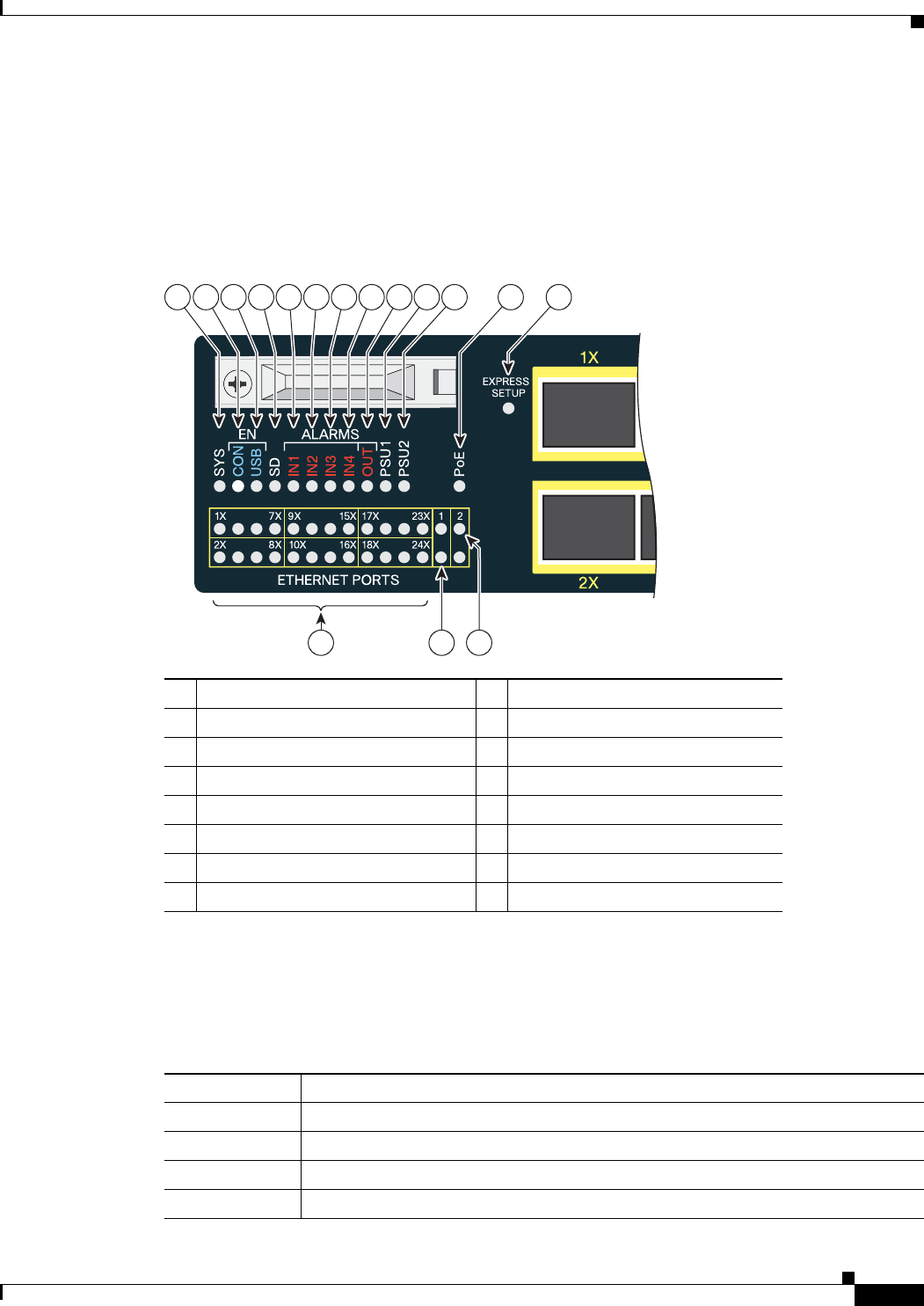
Figure 1-6 Switch LEDs (Cable Side)
System LED
1 SYS (system) 9 OUT (alarm output)
2 CON (console) 10 PSU1 (power supply 1)
3 USB 11 PSU2 (power supply 2)
4 SD (SD flash memory card) 12 PoE
1
1. Only on the Cisco CGS-2520-16S-8PC switch.
5 IN1 (alarm input 1) 13 Express Setup button
6 IN2 (alarm input 2) 14 Ethernet ports
7 IN3 (alarm input 3) 15 SFP module port
8 IN4 (alarm input 4) 16 10/100/1000 port
Table 1-3 System LED
Color System Status
Off System is not powered on
Blinking green POST
1
is in progress
Green System is operating normally
Amber System is receiving power but is not functioning properly
207198
21 3 45678 9 10 11 12 13
14 15
16