


Special offers from our partners!

Find Replacement BBQ Parts for 20,308 Models. Repair your BBQ today.

21
9
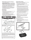
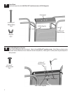
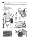
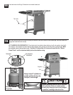
Burner ,Firebox and Control Knob
Place firebox onto cart. Position the heat shield for tank as shown. Attach with #10-24x1-1/4’’ carriage bolts, 7x15 fiber
washers and #10-24 wing nuts ( A).
Place the heat shield for UFC onto burner venturi tube, then insert burner / heat shield through venturi holes on firebox.
Make sure ignitor wire go through th hole on heat shield and firebox as shown (B). Place burner assembly into firebox.
Make sure venturi tubes and valves are correctly engaged. Place small end of venturi clip into venturi tube and large part
of clip around valve (D). If burner is not leveled from left to right, adjust the two screws attaching valve to control panel in
step 8.
Inside firebox, attach firebox and control panel with 5x15 fiber washers and #8-32x3/8’’ sheet metal screws ( C ).
Attach ignitor wire to electrode (D).
Place control knobs on valves as shown (E).
□
□
□
□
□
B
C
D
E
Heat Shield F/Tank
#10-24x1-1/4’’
Carriage bolt
Qty.4
#10-24
Wing Nut
Qty.4
7x15
Fiber Washer
Qty.4
#8-32x3/8’’
Sheet Metal Screw
Qty.2
5x15
Fiber Washer
Qty.2
Venturi Clip
Qty.2
Ignitor wire
Burner Assembly
Knob
#10-24x1-1/4’’ Carriage Bolt
7x15 Fiber Washer
#10-24
Wing Nut
Heat Shield F/UFC
#8-32x3/8’’
Sheet Metal Screw
7X15
Fiber Washer
Venturi Clip
A
Correctly assembled valve in burner tube and venturi clips
Ignitor Wire