


Special offers from our partners!

Find Replacement BBQ Parts for 20,308 Models. Repair your BBQ today.

7
50004825
VM508K / VM658K Assembly
CAUTION: Some parts may have sharp edges; to avoid injury, wearing gloves during assembly, lifting or mov-
ing the grill is recommended.
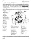
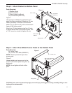
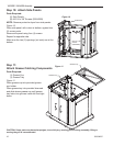
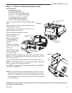
Step 6: Attach Back Panel & Tank
Support
Parts Required:
(1) Back Panel
(4) #10-24 x 3/8” Screws (50004268)
(1) Tank Retainer (LP Model) (VM508K Model)
(1) 1¹⁄₂” OD Bushing (NG Model)
(1) Pull Out Tank (LP Model) (VM658K Model)
Figure 5
Attach back panel to the back of the unit using
four (4) #10-24 x 3/8” screws.
NOTE: For VM508K LP models, attach tank re-
tainer. For VM658K LP models attach pull out tank
assembly. (Follow Pull Out Tank assembly instruci-
tons) For all NG models, attach 1¹⁄₂” OD bushing.
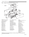
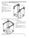
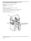
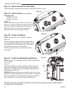
Step 7: Attach Door Assembly and Door Handle
Back Panel
Tank Retainer
(LP Models)
#10-24 x
3/8” Scres
(50004268)
1¹⁄₂” OD Bushing
(Natural Gas
Models)
B145
Figure 5
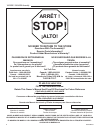
CAUTION
MISE EN
GARDE
CUIDADO
Door Assembly
#10-24 x 3/8” Screws
(50004268)
Handle
w/Screws
B146
Figure 6
Parts Required:
(2) Door Assemblies
(2) Door Handles (w/ Mounting Screws)
(8) #10-24 x 3/8” Screws (50004268)
Figure 6
Attach one (1) door handle to each door as-
sembly using two (2) screws provided with
the handle.
NOTE: Door with caution label - right side.
Attach door assembly with door handle to
the front left and front right cabinet corner
posts.
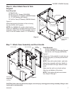
Make sure the unit is on a level surface.
Align top and bottom of the doors.
NOTE: Fully tighten all bolts and screws
from Steps 3 through 7.
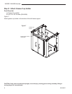
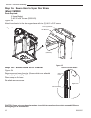
Back
Panel
Routing for
Natural Gas
Supply Hose
to House
Caution Label