


Special offers from our partners!

Find Replacement BBQ Parts for 20,308 Models. Repair your BBQ today.

15
50004825
VM508K / VM658K Assembly
CAUTION: Some parts may have sharp edges; to avoid injury, wearing gloves during assembly, lifting or mov-
ing the grill is recommended.
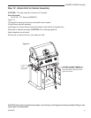
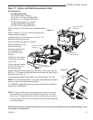
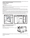
Step 17: Attach Left Shelf Assembly to Grill
Parts Required:
Left Shelf Assembly
(1) Left Shelf Assy. (Step 6)
(4) 1/4-20 x 1¹⁄₂” Screws (50001383)
(4) #10-24 x 1/2” Screws (50000337)
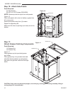
(1) Marinating Station Tray Plastic
(1) Heat Shield Marinating Tray
(2) #10-24 K-lock Nut (50000182)
Refer to Figures 15 & 16 for shelf assembly attach-
ment
Refer to Figures 17 & 18 for heat shield and mari-
nating station installation
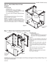
Loosely screw in (4-5 turns) four (4) 1/4-20 x 1¹⁄₂”
screws to the side of the grill.
Place left shelf assembly onto screws.
Secure (tighten) four (4)
screws to the grill.
Secure condiment tray
to the console with
two (2) #10-24 x 1/2”
screws.
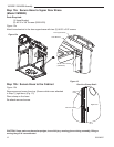
Tighten two (2) remain
-
ing screws. (from Step
15 and 16)
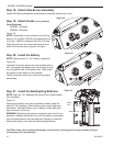
From inside grill, attach
10-24 x 1/2” screw to
the left shelf assy.
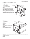
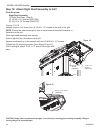
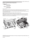
Attach heat shield marinating tray to left side of grill. Insert two (2)
#10-24 x 1/2” screws through grill side and secure with two (2) #10-
24 K-lock nuts. (Fig. 17)
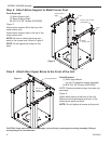
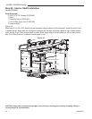
Insert marinating station tray plastic into left side shelf. (Fig. 18)
NOTE: For side shelf opening: if you have any problems opening or
closing, loosen the hinge bolts and adjust.
For VM658K, install shelf light according to Electronics Installation
Instructions, #50003699.
NOTE: For grill models with a marinating station: Loosen the two (2)
bolts and nuts securing the heat shield marinating tray to the grill
body. (Fig. 17) Attach the rotisserie motor bracket using the same
mounting holes. Secure both the bracket and heat shield using bolts
and nuts provided.
#10-24 x 1/2” Screws
(50000337)
Heat Shield
Marinating Tray
#10-24 K-lock Nuts
(50000182)
B183
Figure 17
Marinating
Tray
Figure 18