


Special offers from our partners!

Find Replacement BBQ Parts for 20,308 Models. Repair your BBQ today.

7
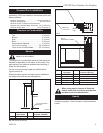
ODGSR Series Outdoor Gas Fireplace
20007114
FP1414
ODUVSR
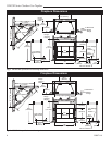
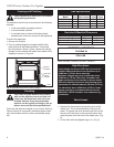
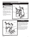
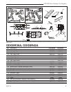
valve access
11/24/03 djt
FP1414
Fig. 5 Valve access.
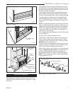
FP1415
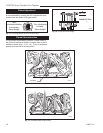
lift brick access
11/24/03 djt
Majestic Logo
Brick
Fig. 6 Lift brick with logo on it to access valve.
FP1415
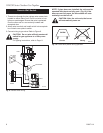
FP1416
ODUVSR
part id
11/24/03 djt
Nailing
Flange
Valve Access Panel
Firebox
Grate
Screen
Standoff
Surround
Gas
Line Ac-
cess
FP1416
Fig. 7 Parts identification.
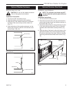
*Do not install
header until unit
is in place.
Gas Line Installation
This appliance must be isolated from the gas supply
piping system by closing its individual manual shut off
valve during any pressure equal to or less than 1/2 psig
(3.45 kPa).
The appliance and its individual shutoff valve must be
disconnected from the gas supply piping system during
any pressure testing of that system at test pressures in
excess of 1/2 psig (3.45 kPa).
If gas piping from the source to the appliance location
has not been accomplished, install the required pipe.
Consult local plumbing code to assure proper pipe size.
The gas pipeline can be brought in through the right
side of the appliance. A knockout is provided to allow
for the gas pipe installation and testing of any gas con-
nection.
NOTE: The gas line connection can be made with 3/8"
copper tubing approved for propane or natural gas, 1/2"
rigid pipe or an approved flex connector, then reduced
to 3/8" to the appliance. Because some municipalities
have some additional local codes, it is always best to
consult your local authority.
U.S.: Consult the current National Fuel Gas Code, ANSI
Z223.1/NFPA 54.
Canada: CSA - B149.1 installation code.
Test for leaks. Use a 50/50 solution of liquid soap and
water to test for leaks at gas fittings and joints. Apply
water/soap solution with brush only - do not over apply.
NEVER test with an open flame.
The gas control is equipped with a captured screw type
pressure test point, therefore it is not necessary to pro-
vide a 1/8" test point up stream of the control.
When using copper or flex connector use only approved
fittings.
Always provide a union so that gas line can
be easily disconnected for burner or fan servicing.
See gas specification for pressure details and ratings.
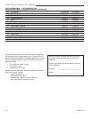
NOTE: If flex connector is used, it must be kept inside
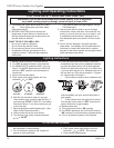
of the appliance. (Fig. 8)
FP598
Fig. 8 Typical gas supply installation.
GF598
nvb GAS SUPPLY INSTALL
12/4/97
1/2" Gas Supply
1/2" x 3/8" Shut-off Valve
3/8" Nipple
3/8" Union
3/8" Nipple