


Special offers from our partners!

Find Replacement BBQ Parts for 20,308 Models. Repair your BBQ today.

7
Vermont Castings Gas Patio Fire
Installation of GPF on
Optional Chalet Base
The Chalet Base is designed as a decorative enhance-
ment for use with the Gas Patio Fire.
Tools required: 7/16”, 3/4” and 11/16” wrenches, phillips
screwdriver.
Installation Instructions
1. Remove Chalet Base assembly from shipping
carton. Remove two (2) 1/4-20 fasteners and two (2)
washers from the cast valve panel, set aside.
2. Remove the four (4) sheet metal screws that hold
the valve brackets to the burner on the GPF and
discard.
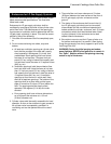
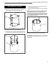
3. Disconnect the fuel supply line from the valve using
a 3/4” wrench. (Fig. 7) Using both the 3/4” and 11/16”
wrenches, remove the fuel supply line from the venturi
(tube secured to the bottom of the burner). Assemble
the valve and bracket assembly to the Chalet using the
1/4-20 x 1/2” fasteners and washers removed in Step 2.
Reconnect the fuel supply line to the valve and tighten.
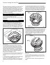
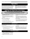
Feed the fuel line from the gas supply through the fuel
line opening in the base. Place the octagonal mounting
plate on the Chalet. (Fig. 8) Orient the plate with the
long side of the rectangular opening parallel to the
valve panel. Pass the fuel line through the rectangular
opening and reconnect the fuel supply line to the
venturi on the GPF and tighten using the 3/4” and
11/16” wrenches.
4. Seat the GPF burner assembly on the Chalet. Pass
the burner legs through the rectangular opening in the
plate. (Fig. 8)
5. Continue with volcanic rock and log placement on
page 7.
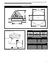
Cast Valve Panel
Valve
Valve Brackets
KT264
Fig. 7 Attach valve and brackets to cast valve brackets.
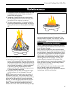
Log & Volcanic Rock Placement
Remove logs from packaging and examine each for
damage. If any logs are damaged or missing, contact
your dealer. DO NOT install damaged logs.
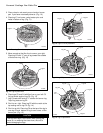
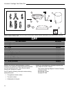
Volcanic Rock Placement
Pour volcanic rock into outer ring and over burner.
Make sure the volcanic rock is level with the outer ring
and builds up to cover the burner.
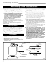
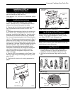
Log Placement
1. Arrange logs on floor near burner according to
Figure 9. As shown in Figure 9, the bottom of the
logs will be toward the outside of the burner ring.
2. Use flex line as reference. Begin with line to your
left.
C1
C2
C3
C4
C5 C6
Fig. 9 GPF logs.
LG161
GPF Burner
Assembly
Octagonal
Plate
Cast
Valve
Panel
Valve and Bracket
KT263
Fig. 8 Cutaway section of Chalet Base.
Locator Pins
Burner Pan
Volcanic Rock
Flex
Line
Burner
Ring
Fig. 10 Arrange volcanic rock evenly around and on burner
pan.